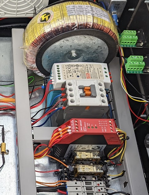
Novice here with zero knowledge and experience of industrial control, please forgive the lengthy post. I have read and searched numerous threads here as well as YouTube videos to ad nauseam and been at it since 0430 this morning with only frustration to show for it. Here is my setup of a DIY PrintNC machine:
- "Axis" 3-axis configuration, X, Y1, Y2, Z.
- Mesa 7i76E.
- 120VAC 2.2kW water-cooled spindle (Z-mounted, but not connected to VFD).
- Huanyang VFD (powers up).
- PNP proximity sensors at both ends of X, Y1, and Y2. Z only has software limits defined.
- Prox sensors wired to 3-wire PLC input module, 6-way sensor terminal block with the signals wired to Mesa digital-in. HAL "sees" the states of the prox sensors which appropriately change when triggered. Home and min/max limits have not been defined - yet. That is for another day. At the moment only software limits defined for all axis.
- Main multi-branch power circuit enters emergency "oh sh*t" paddle switch mounted to the enclosure, much like a table saw or router table. Pushing the paddle terminates power to the entire enclosure, everything turns off - motion and control.
- From paddle switch, multi-branch main power circuit enters enclosure to door mounted two-position lock-out type main power rotary switch. One branch is power for typical 2-button 120VAC 24VDC coil contactor holding circuit, attached to it is all motion (VFD and D542 drivers). Power to motion side can be killed entirely as expected with the holding circuit being turned "off". The other phase provides power to the control side (Mesa, exhaust fan, and other peripheries). The control side power is turned off when the main power rotary switch is turned off.
What additional hardware is needed to implement a hardware e-stop and a reset function? I do not wish to route main 120V through e-stop buttons, rather like to keep it inside the enclosure. I only have e-stop NO/NC mushroom buttons of various styles and hole diameters. Nothing else. I've read the "External Power On/Off + EStop" and "Emergency STOP on mesa card 7i76e" threads several times. Please interject and correct my understanding of how to proceed:
- Connect a Mesa TB1 field power output (pin 0-3) to the NO in terminal of the e-stop button. Using more than one e-stop button requires wiring the NO circuitry in parallel so that a possible malfunctioning switch along the chain does not cause an unwanted e-stop signal - the switch must be intentionally depressed by human action.
- Connect the e-stop NO out terminal to Mesa digital-in pin (TB5 or TB6, pin number to determined for coding in HAL). This is the e-stop pressed "event notification" signal. In my case it is 24VDC.
- Connect Mesa digital-out (TB5 or TB6, pin number to be determined for coding in HAL) to +VDC terminal of solid-state relay.
Q: This and the GND connection will cause the relay to energize its coil and open (if NC relay) thereby removing the +5V signal from Mesa to the stepper drivers ENA+, thereby "disabling" them so they no longer output Step/Dir pulses to the stepper motors? Is that its intent?
Q: Does not removing power to ENA+ cause the stepper motors to stop moving? Power to them can be left on?
Q: Do I need a SPDT or DPDT and what kind NO only, NO/NC, NC only? I ordered two of these based on Rod's recommendation in one of the aforementioned threads, is this correct?
Ultrathin DIN Rail Relay Module, MRD-060D2, Input 4-32VDC NO
- Connect Mesa GND to -VDC terminal of solid-state relay.I think I am a-OK to this point. My conundrum is the "load" side of the relay. Stepper drivers ENA+ can accept +5V~24V and they and accompanying ENA- are NOT connected on my machine.
Q: Does that signal pulse have to come from the +5V terminal of one of the unused Mesa Step/Dir output connectors on TB2 or TB3? Does this Step/Dir output need to be added to the system configuration if I did not select 5 steppers in configuration wizard? It isn't being used as step/dir controller, how does the +5V terminal actually go high?
Q: Could the signal instead come from one of the Mesa digital-out terminals of TB5 or TB6 with a buck/step-down converter reducing the 24VDC to 10VDC max and programmed in HAL appropriately? Only need an "on" signal, right? I suppose the buck converter is another point of possible hardware failure to contend with.
- Connect Mesa GND to D542 ENA- terminal.
Q: Does it actually matter the source of the Mesa ground? Could it be a "field ground" (terminal block connected to Mesa TB1 or to TB3 supply power ground) or does it have to also come from the same unused/spare Step/Dir output connector supplying the +5V?
- Daisy-chain connect each of the D542 stepper driver's +ENA and -ENA.
Now the part I need the most help with. What to do with the NC branch of the E-Stop button in order to to stop I guess the power to the VFD? Should power to it be removed entirely or should the output speed, direction, etc. to the spindle be turned "off" - and how? Another relay and routing through Mesa?
Thank you.
Darryl