Search Results (Searched for: )
- AndyDM01
- AndyDM01
30 Jul 2024 16:44
Replied by AndyDM01 on topic Ethercat build from source - full instructions
Ethercat build from source - full instructions
Category: EtherCAT
- my1987toyota

30 Jul 2024 16:36 - 30 Jul 2024 17:07
Replied by my1987toyota on topic Was the SPAM topic a test
Was the SPAM topic a test
Category: Off Topic and Test Posts
- my1987toyota
30 Jul 2024 16:14 - 30 Jul 2024 16:17
Replied by my1987toyota on topic Was the SPAM topic a test
Was the SPAM topic a test
Category: Off Topic and Test Posts

- my1987toyota
30 Jul 2024 15:50
Replied by my1987toyota on topic Interesting Youtube Video
Interesting Youtube Video
Category: Off Topic and Test Posts
- my1987toyota
30 Jul 2024 15:37
Replied by my1987toyota on topic Who wants to use MODBUS ? Video.
Who wants to use MODBUS ? Video.
Category: Off Topic and Test Posts
- my1987toyota
30 Jul 2024 15:33 - 30 Jul 2024 16:01
Replied by my1987toyota on topic Was the SPAM topic a test
Was the SPAM topic a test
Category: Off Topic and Test Posts
- cakeslob
- cakeslob
30 Jul 2024 15:25
Replied by cakeslob on topic Remora - ethernet NVEM / EC300 / EC500 cnc board
Remora - ethernet NVEM / EC300 / EC500 cnc board
Category: Computers and Hardware
- AirRacer
- AirRacer
30 Jul 2024 15:09
Replied by AirRacer on topic Mesa CT Huge Improvements Coming
Mesa CT Huge Improvements Coming
Category: Driver Boards
- Krulli_Fräser
- Krulli_Fräser
30 Jul 2024 14:48
Replied by Krulli_Fräser on topic Verify my Mesa selection
Verify my Mesa selection
Category: Driver Boards
- PCW

30 Jul 2024 14:47
- manfrel
- manfrel
30 Jul 2024 14:22
Replied by manfrel on topic Mesa 7i96s + DM556T -> Motors not moving
Mesa 7i96s + DM556T -> Motors not moving
Category: Driver Boards
- ffffrf
- ffffrf
30 Jul 2024 13:56 - 30 Jul 2024 13:57
Replied by ffffrf on topic help with millrun and/or custom Z-X-A(or C) lathe/machine
help with millrun and/or custom Z-X-A(or C) lathe/machine
Category: Fusion 360
- ffffrf
- ffffrf
30 Jul 2024 13:32
help with millrun and/or custom Z-X-A(or C) lathe/machine was created by ffffrf
help with millrun and/or custom Z-X-A(or C) lathe/machine
Category: Fusion 360
- Grotius

30 Jul 2024 13:12 - 30 Jul 2024 14:20
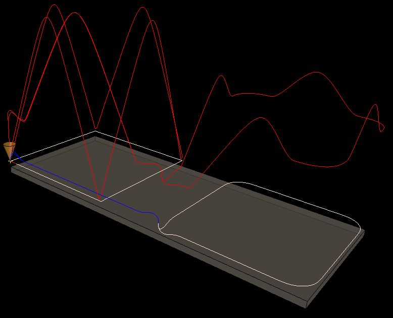
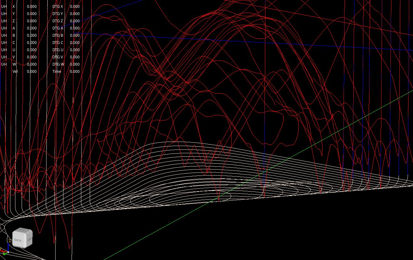
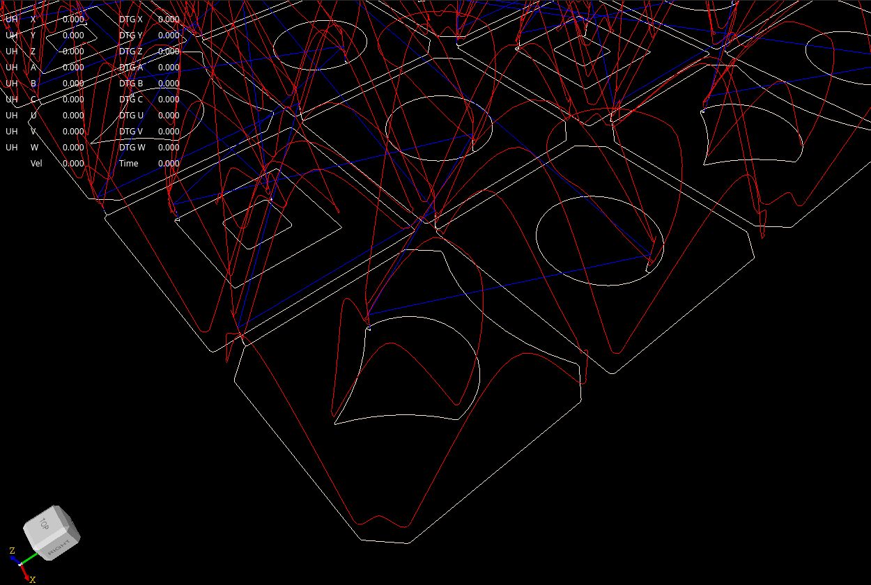
Replied by Grotius on topic Trajectory Planner using Ruckig Lib
Trajectory Planner using Ruckig Lib
Category: General LinuxCNC Questions
- spumco
- spumco
30 Jul 2024 13:05
Replied by spumco on topic Which Mesa Card Should I Buy?
Which Mesa Card Should I Buy?
Category: Driver Boards
Time to create page: 0.701 seconds