Trajectory Planner using Ruckig Lib
- Aciera
-

- Offline
- Administrator
-

Less
More
- Posts: 4724
- Thank you received: 2117
27 Jul 2024 10:47 #306166
by Aciera
Replied by Aciera on topic Trajectory Planner using Ruckig Lib
Yes, but really this would only produce a time _optimized_ tool path as the max-curvature would need to be exceeded in some corner segments that are not long enough.You mean, check until a minmal given feed is valid over the path? This feed input creates the fillet size's?
This is holy grail? Haha.
The following user(s) said Thank You: akb1212, Lcvette, Grotius
Please Log in or Create an account to join the conversation.
- Grotius
-

- Offline
- Platinum Member
-

Less
More
- Posts: 2419
- Thank you received: 2348
27 Jul 2024 13:27 #306174
by Grotius
Replied by Grotius on topic Trajectory Planner using Ruckig Lib
Hi Arciera,
A time optimal algo we can add on the todo list. It's really interesting to code this, and see the results.
I have no idea how difficult it is to code this.
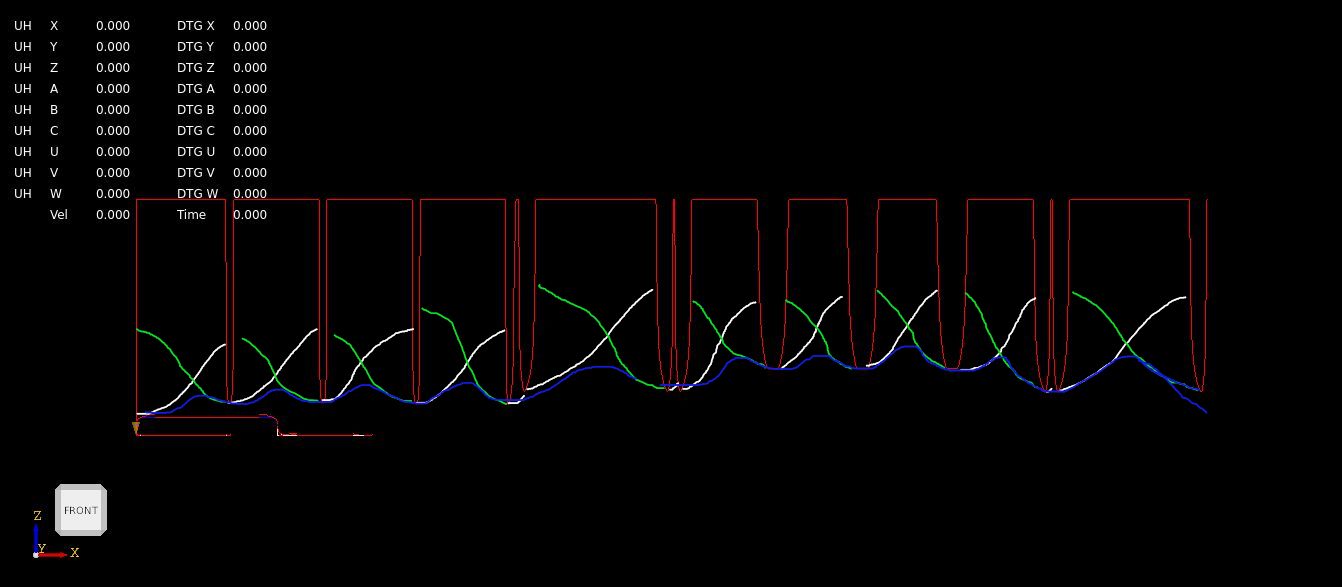
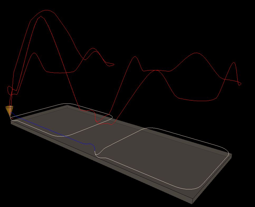
For now i plotted the trajectory path lenghts vs the velocity profile on the xz plane.
Then for fitting the scurve on the trajectory (look ahead), we could do a forward sweep in white.
Then a backward sweep in green.
Then get the create a final blue curve that is below the green & white curve.
The blue curve is the overall path velocity profile. I think this should be correct.
A time optimal algo we can add on the todo list. It's really interesting to code this, and see the results.
I have no idea how difficult it is to code this.
For now i plotted the trajectory path lenghts vs the velocity profile on the xz plane.
Then for fitting the scurve on the trajectory (look ahead), we could do a forward sweep in white.
Then a backward sweep in green.
Then get the create a final blue curve that is below the green & white curve.
The blue curve is the overall path velocity profile. I think this should be correct.
Attachments:
The following user(s) said Thank You: akb1212, Lcvette, Aciera, tiagounderground
Please Log in or Create an account to join the conversation.
- Aciera
-
- Offline
- Administrator
-
Less
More
- Posts: 4724
- Thank you received: 2117
27 Jul 2024 13:46 #306175
by Aciera
Replied by Aciera on topic Trajectory Planner using Ruckig Lib
What is the line in red and how do you choose the start velocity for a segment in the forward and backward sweep?
The following user(s) said Thank You: akb1212, Lcvette, Grotius
Please Log in or Create an account to join the conversation.
- Grotius
-
- Offline
- Platinum Member
-
Less
More
- Posts: 2419
- Thank you received: 2348
27 Jul 2024 15:25 #306177
by Grotius
Replied by Grotius on topic Trajectory Planner using Ruckig Lib
Hi Arciera,
The red is the vm based on curvature.
Forward sweep starts at zero vel. Backwards sweep start at zero vel.
Then the algo has to look if the velocity may be increased or not.
The red is the vm based on curvature.
Forward sweep starts at zero vel. Backwards sweep start at zero vel.
Then the algo has to look if the velocity may be increased or not.
The following user(s) said Thank You: akb1212, Lcvette, Aciera
Please Log in or Create an account to join the conversation.
- Aciera
-
- Offline
- Administrator
-
Less
More
- Posts: 4724
- Thank you received: 2117
27 Jul 2024 15:40 #306178
by Aciera
Replied by Aciera on topic Trajectory Planner using Ruckig Lib
I see.
Very handy to have these graphs. Like hal-scope for the preview.
Very handy to have these graphs. Like hal-scope for the preview.
The following user(s) said Thank You: akb1212, Lcvette, Grotius
Please Log in or Create an account to join the conversation.
- Lcvette
-

- Offline
- Platinum Member
-
Less
More
- Posts: 1627
- Thank you received: 757
28 Jul 2024 15:52 #306243
by Lcvette
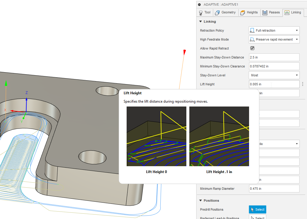
In fusion there is a setting for lift height which is a very small movement just to lift the tool gently above the previously cut surface while repositioning to the next engagement point, this lift height could certainly be set very near the same value used for the G64 P value in cam. in this example the lift height is set at 0.005" which would mean if a P value is set at 0.004" (default smoothing value used in fusion for adaptive roughing cycles) it would not be able to remain between the Z start/end positions correct? or am i wrong here? I have attached the settings in cam along with the code as it would be posted, perhaps you could plug it in to see the results with the new planner?
Thanks, let me know if you need anything else!
Chris
Replied by Lcvette on topic Trajectory Planner using Ruckig Lib
Grotius,I don't think this is practical as the operator would have to keep this in mind for every possible machining operation.
Yes, and on the other hand, i showed an exceptional case. Normally a travel height would be like 1 up to 50mm and
a G64 P0.01 for the fillets. This will not be a problem at all.
In fusion there is a setting for lift height which is a very small movement just to lift the tool gently above the previously cut surface while repositioning to the next engagement point, this lift height could certainly be set very near the same value used for the G64 P value in cam. in this example the lift height is set at 0.005" which would mean if a P value is set at 0.004" (default smoothing value used in fusion for adaptive roughing cycles) it would not be able to remain between the Z start/end positions correct? or am i wrong here? I have attached the settings in cam along with the code as it would be posted, perhaps you could plug it in to see the results with the new planner?
Thanks, let me know if you need anything else!
Chris
Attachments:
The following user(s) said Thank You: akb1212, Grotius
Please Log in or Create an account to join the conversation.
- Grotius
-
- Offline
- Platinum Member
-
Less
More
- Posts: 2419
- Thank you received: 2348
28 Jul 2024 21:33 #306281
by Grotius
Replied by Grotius on topic Trajectory Planner using Ruckig Lib
@Lcevette,
In previous post somewhere:
the travelheight has to be at least the G64 P..
in this example the lift height is set at 0.005" which would mean if a P value is set at 0.004"
Then you could use : lift height 0.005 and P0.005. Then it will not go down the z.
Thanks for the gcode file. It loads, but i have some spline problems i see. Haha. I see a lot of spagetti.
So i have to look what's going on and fix it. When it's fixed i will let you know about the file fillets and how they behave.
I had solved a weird thing in the gcode parser.
To convert a string to a double value, some times this failed on other linux pc. It had to do with value using . or , as decimal seperator
as input for the std::stod function.
It's solved by adding : std::locale::global(std::locale("C"));
Thanks, let me know if you need anything else!
A bit off luck... Haha.
Today i coded some more for the look ahead.
I think based on previous post, where the red line of the graph is the velocity profile based on curvature of segments.
This then can be used to retrieve the vo,vm,ve for the trajectory planner.
Arciera mentioned earlyer, the clothoid fillets are quite small, so let we use a vo,vm,ve for each segment.
The following user(s) said Thank You: akb1212, Lcvette
Please Log in or Create an account to join the conversation.
- Grotius
-
- Offline
- Platinum Member
-
Less
More
- Posts: 2419
- Thank you received: 2348
30 Jul 2024 11:41 - 30 Jul 2024 11:42 #306397
by Grotius
Replied by Grotius on topic Trajectory Planner using Ruckig Lib
Hi,
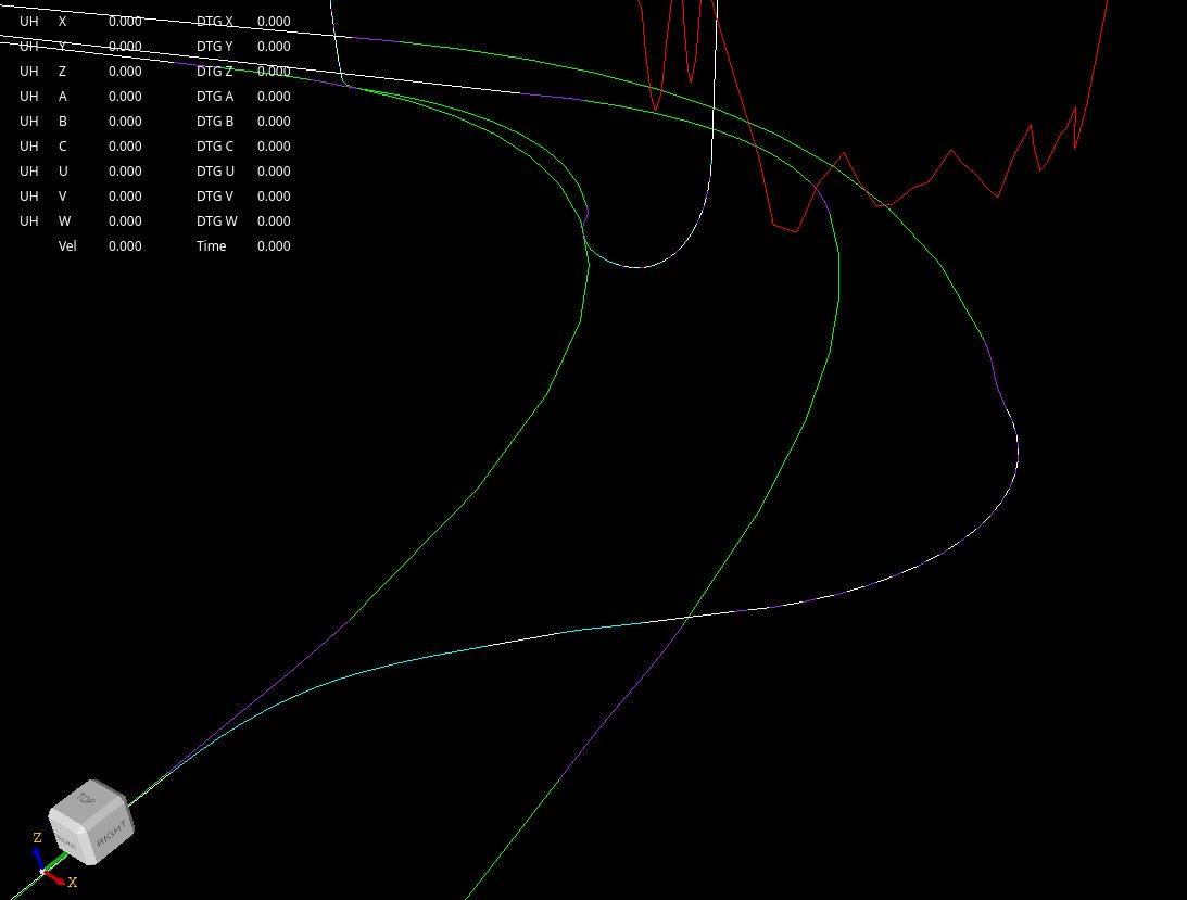
I am now at the point that we have done :
- Calculate the velmax of each segment given the max curvature of that segment.
- Path Vel Optimizer: perform a forward scurve motion over the path, update vo's, ve's if valid.
- Path Vel Optimizer: perform a reverse scurve motion over the path, update vo's, ve's if valid.
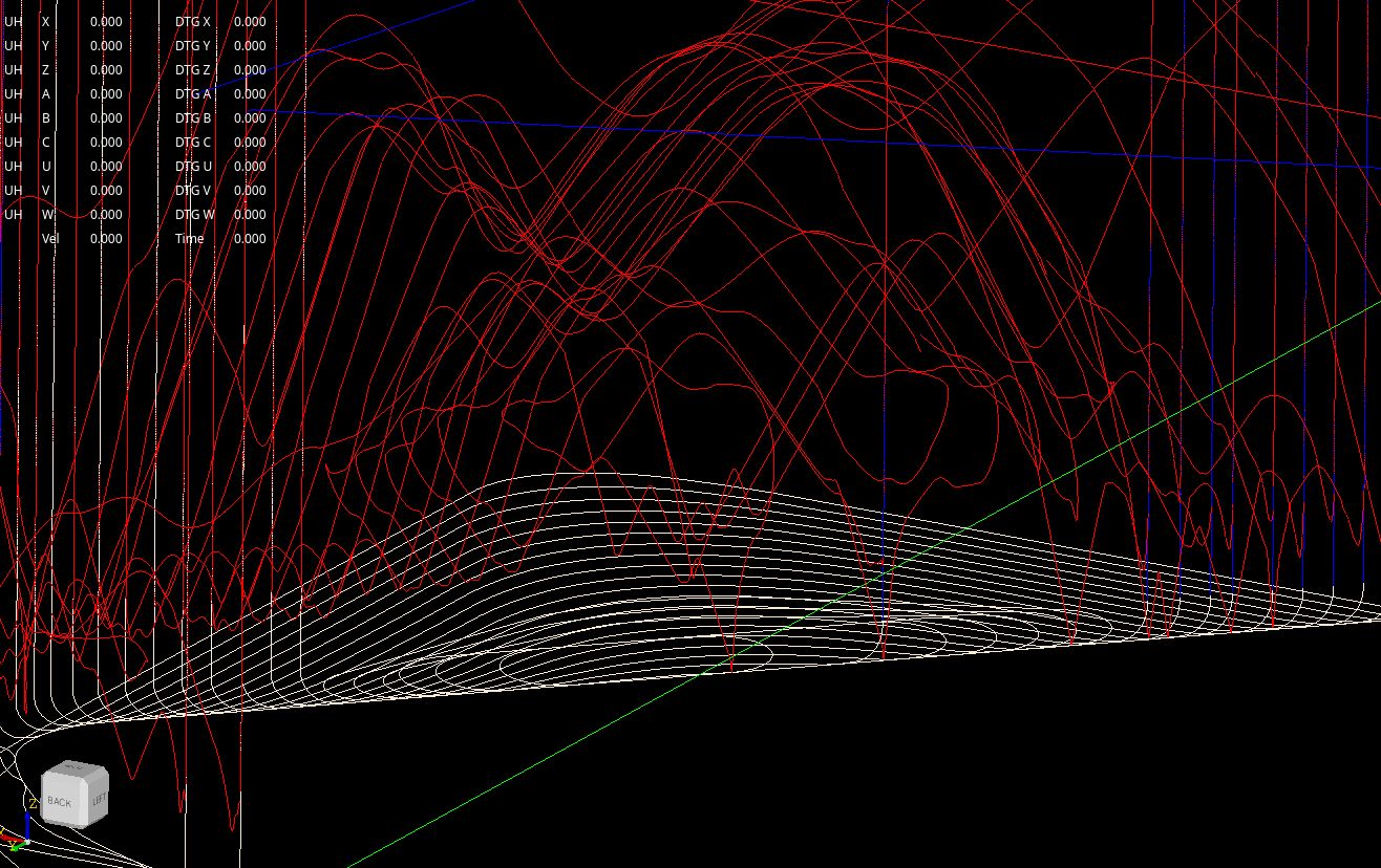
- Plot 2d, 3d velocity profile.
2D velocity profile, the green verticals to z zero, indicates a segment transition.
You see i at the begin of the green curve, i added multiple colinear lines, to test the transition.
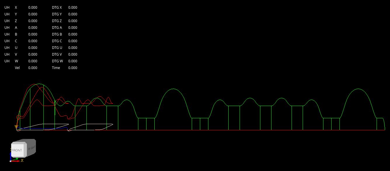
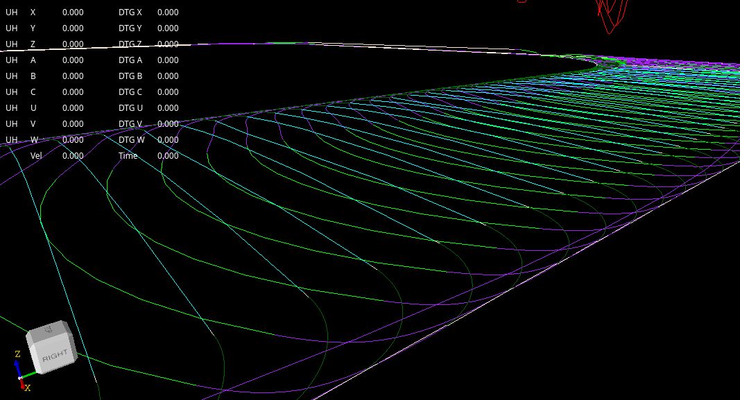
3D velocity profile,
My conclusion so far, if user gives no G64 P.. value. Then P=0. Then no fillet segments are created.
This must be avoided as fillets are ideal to get endvelocity's in line-line corners etc.
So solution is to set a very low P value if P=0 is given.
Then we set P=0.0001, this is valid and creates the fillets, and end velocity's without adding a bunch of extra sourve code.
Then i have seen when max_jerk is set at very low value, the scurve can't keep up and finishes with endvelocity > 0. This
is not ok. So when the Optimizer algo is performed, and the final velocity at the end of the path > 0, then
we must increase the jerk value until a valid output, wich is endvel=0. I have no other solution found for this so far.
I am now at the point that we have done :
- Calculate the velmax of each segment given the max curvature of that segment.
- Path Vel Optimizer: perform a forward scurve motion over the path, update vo's, ve's if valid.
- Path Vel Optimizer: perform a reverse scurve motion over the path, update vo's, ve's if valid.
- Plot 2d, 3d velocity profile.
2D velocity profile, the green verticals to z zero, indicates a segment transition.
You see i at the begin of the green curve, i added multiple colinear lines, to test the transition.
3D velocity profile,
My conclusion so far, if user gives no G64 P.. value. Then P=0. Then no fillet segments are created.
This must be avoided as fillets are ideal to get endvelocity's in line-line corners etc.
So solution is to set a very low P value if P=0 is given.
Then we set P=0.0001, this is valid and creates the fillets, and end velocity's without adding a bunch of extra sourve code.
Then i have seen when max_jerk is set at very low value, the scurve can't keep up and finishes with endvelocity > 0. This
is not ok. So when the Optimizer algo is performed, and the final velocity at the end of the path > 0, then
we must increase the jerk value until a valid output, wich is endvel=0. I have no other solution found for this so far.
Attachments:
Last edit: 30 Jul 2024 11:42 by Grotius.
The following user(s) said Thank You: akb1212, tommylight, Lcvette, Aciera, Darium
Please Log in or Create an account to join the conversation.
- Grotius
-
- Offline
- Platinum Member
-
Less
More
- Posts: 2419
- Thank you received: 2348
30 Jul 2024 13:12 - 30 Jul 2024 14:20 #306402
by Grotius
Replied by Grotius on topic Trajectory Planner using Ruckig Lib
Hi,
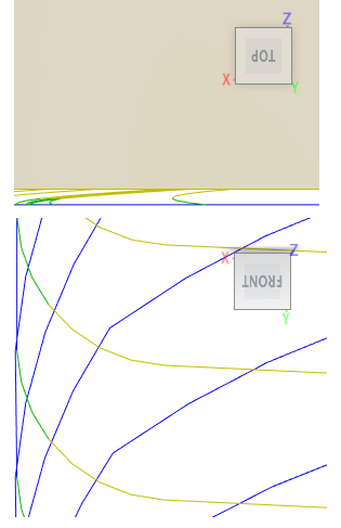
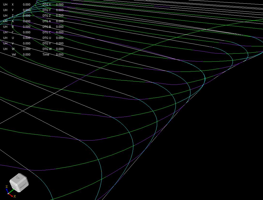
For coleair lines and curves with curvature=0 (clothoid, spline that is in fact a line), i fused them to one piece of type line.
This seems to work better.
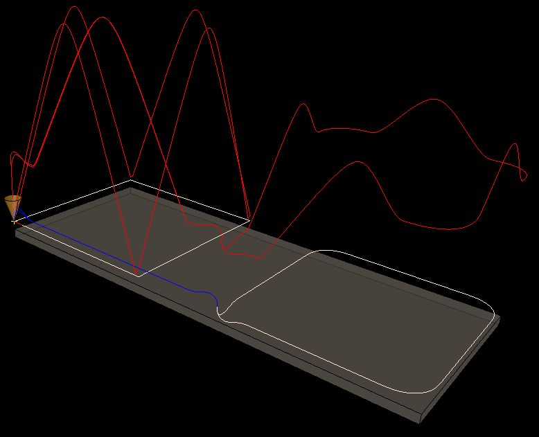
For coleair lines and curves with curvature=0 (clothoid, spline that is in fact a line), i fused them to one piece of type line.
This seems to work better.
Attachments:
Last edit: 30 Jul 2024 14:20 by Grotius.
The following user(s) said Thank You: akb1212, tivoi, pommen, Lcvette, Aciera, Darium, JacobRush, nwallace
Please Log in or Create an account to join the conversation.
- Grotius
-
- Offline
- Platinum Member
-
Less
More
- Posts: 2419
- Thank you received: 2348
01 Aug 2024 12:44 #306605
by Grotius
Replied by Grotius on topic Trajectory Planner using Ruckig Lib
Hi,
I fixed some issue's in the gcode parser, it now loads the lcevette lift_test.ngc file ok.
In gcode we used:G64 P0.05 Q0.05
It filters out tiny lines according Q value.
It add's fillets according the P value. It first try's to add clothoid fillets, then it add's spline fillets.
There is a lot happening performing the algo. Fillets can be made between 2 helixes for example.
Every scenario had to be code.
Overall this is quite a complex task.
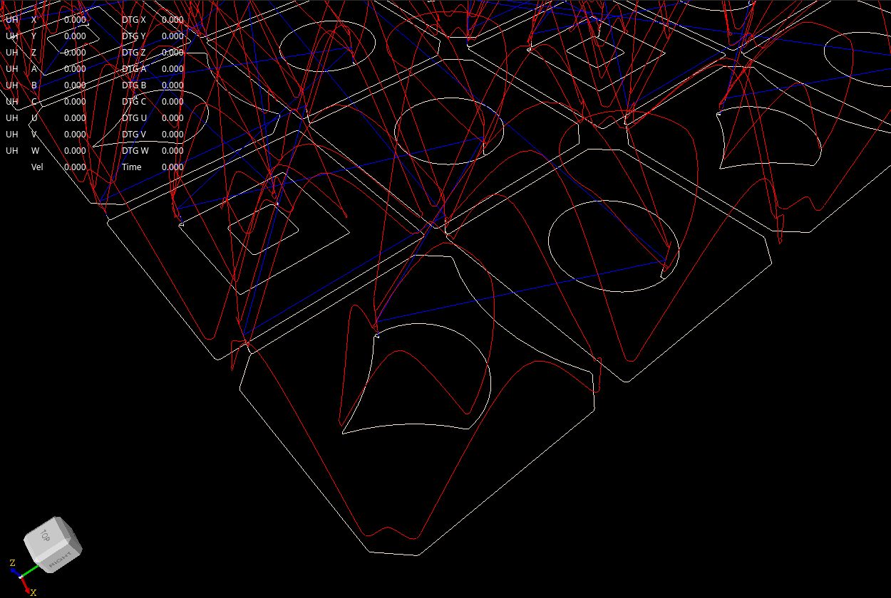
Colors to verify:
red=3d velocity profile.
white=linelight_green=arc
purple=clothoid fillet
cyan=spline fillet
yellow=trimmed helix
dark_green=helix
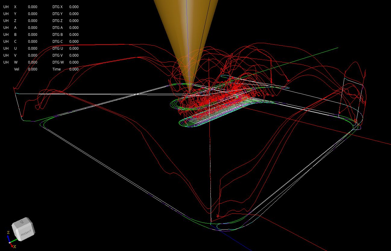
When G64 P0.0 Q0.0 output:
I fixed some issue's in the gcode parser, it now loads the lcevette lift_test.ngc file ok.
In gcode we used:G64 P0.05 Q0.05
It filters out tiny lines according Q value.
It add's fillets according the P value. It first try's to add clothoid fillets, then it add's spline fillets.
There is a lot happening performing the algo. Fillets can be made between 2 helixes for example.
Every scenario had to be code.
Overall this is quite a complex task.
Colors to verify:
red=3d velocity profile.
white=linelight_green=arc
purple=clothoid fillet
cyan=spline fillet
yellow=trimmed helix
dark_green=helix
When G64 P0.0 Q0.0 output:
Attachments:
The following user(s) said Thank You: akb1212, pommen, Lcvette, Aciera
Please Log in or Create an account to join the conversation.
Time to create page: 1.708 seconds