Trajectory Planner using Ruckig Lib
- Aciera
-

- Offline
- Administrator
-

- Posts: 4755
- Thank you received: 2135
unless the minimum radius setting would not allow for the transition to move from the previous line plane to the new line target plane maybe?
Yes, it's likely that the vertical move from the G0 traverse to the G1 contour depth is too short to create a fillet that satisfies the limit of curvature so it basically decides to take the longer route. Not sure how easy it is to detect such cases in the algorithm but it is going to be absolutely crucial to get this rock solid.
Please Log in or Create an account to join the conversation.
- Grotius
-

- Offline
- Platinum Member
-

- Posts: 2419
- Thank you received: 2348
When the travelheight is 20mm and the fillet radius is 20mm the result is valid :
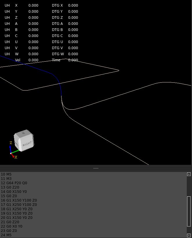
When travelheight is 1mm and the fillet radius is 20mm "G64 P20",
The G0 z line from z1 to z0 is 1mm. This line is then trimmed by the algo on both sides
back to minimal lenght ~0.001mm, as it can not be trimmed back 20mm.
The attached line on the xy plane, the next gcode line,
is long enough to be trimmed back 20mm on both sides,
so when this happens, the clothoid curve will go below the xy plane in z.
Technically this is correct to do so for the algoritme. In practical sence this is unwanted for the workpiece.
As it damages the surface.
One solution: In cam programs, the travelheight has to be at least the G64 P..
Another solution: In the fillet algo, we could measure the rapid heights for G0's rapids and use this as a max for the G64 P.. value.
We have to do this for each plane, G17, G18, G19. But then still if you use G1 rapids, it still create's a fillet that
damages workpiece.
Attachments:
Please Log in or Create an account to join the conversation.
- Aciera
-
- Offline
- Administrator
-
- Posts: 4755
- Thank you received: 2135
One solution: In cam programs, the travelheight has to be at least the G64 P..
I don't think this is practical as the operator would have to keep this in mind for every possible machining operation. Checking the filleting result in a GCODE file with thousands of lines is simply not possible and even if this were a settable global cam option it would mean that a change in G64 P value required running everything through the CAM again.
So, if the algorithm realizes that the segment cannot be trimmed by the required distance it would seem possible to handle these cases separately. Either just don't create a fillet at all or create a fillet with a bigger curvature.The G0 z line from z1 to z0 is 1mm. This line is then trimmed by the algo on both sides
back to minimal lenght ~0.001mm, as it can not be trimmed back 20mm.
Something else I would like to ask is the meaning of the P value, currently it seems to be the distance a segment is trimmed back but really what the operator wants to know is the maximum deviation from the end/start point this is going to create. In the papers I've read about filleting algorithms the process is actually iterative. After a fillet is created the maximum deviation is calculated. If the deviation is over the acceptable limit the filleting parameters are changed, the fillet is created again and the deviation is again checked. This runs until the maximum deviation is below the limit (ie below the P value).
To be honest, I have no idea how difficult it is to calculate the maximum deviation a clothoid fillet creates from the original line segments but without the ability to precisely define a maximum value for path deviation I'd be _very_ reluctant to use a filleting algorithm.
Please Log in or Create an account to join the conversation.
- Aciera
-
- Offline
- Administrator
-
- Posts: 4755
- Thank you received: 2135
Please Log in or Create an account to join the conversation.
- Aciera
-
- Offline
- Administrator
-
- Posts: 4755
- Thank you received: 2135
Start the iteration with a very small trim-back value and increase until either
a) the deviation exceeds the maximum set by the P value
b) one to the original path segments gets too short
Please Log in or Create an account to join the conversation.
- Aciera
-
- Offline
- Administrator
-
- Posts: 4755
- Thank you received: 2135
While a constant maximum deviation will create a shorter fillet with higher curvature. This will of course mean a decrease in tool velocity but brings the necessary certainty about maximum path deviation.
Please Log in or Create an account to join the conversation.
- Grotius
-
- Offline
- Platinum Member
-
- Posts: 2419
- Thank you received: 2348
The G64 P.. value stands for max path deviation.
Current implementation uses the P value as a trim value for corners and then
create fillet. This results in a deviation less then should be.
It's done this way for now, to keep it simple and get things to work. Adding loops to the code to get as close
to the real path deviation is possible for sure. This code change is on the todo list.
say 25%, 50% and 75% of the total length of the trimmed segments and compare those to the 3d coordinates
Path deviation check at progress t=0.5 of the fillet segment to original path is ok to find closest value of P..
If that is what you mean?
I don't think this is practical as the operator would have to keep this in mind for every possible machining operation.
Yes, and on the other hand, i showed an exceptional case. Normally a travel height would be like 1 up to 50mm and
a G64 P0.01 for the fillets. This will not be a problem at all.
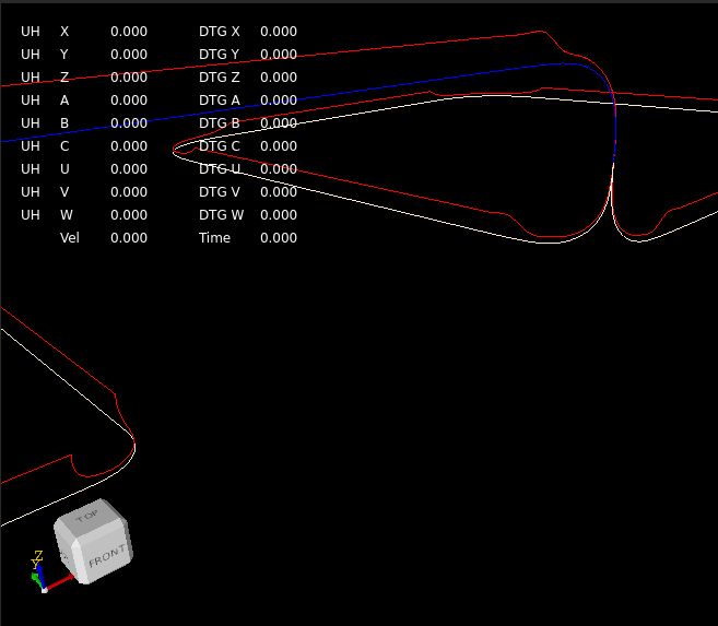
Here we tested a velocity profile based on current curvature along the path.
The red line is a interpolated velocity offset along the path based on the shape's curvature input.
This is interesting.
*Note that the line has zero curvature and speed is constant.
*Note in the lower left of the picture the red line has sharp transition corners, this has a reason i figured out.
The maxvm for the path is set at 250. The clothoid at curvature=0, may have a higher speed and it lowered down.
This results in a sharp speed transition edge.
Attachments:
Please Log in or Create an account to join the conversation.
- Aciera
-
- Offline
- Administrator
-
- Posts: 4755
- Thank you received: 2135
I'm not sure if you envisioned using the filleting algorithm to optionally create feed optimized roughing paths but if you did this we could then abandon the max-deviation value and use a minmal-curvature value instead. The algorithm would then increase the trim-back until either
a) minimal-curvature value is reached
b) one of the original path segments gets too short.
Please Log in or Create an account to join the conversation.
- Grotius
-
- Offline
- Platinum Member
-
- Posts: 2419
- Thank you received: 2348
optionally create feed optimized roughing paths
You mean, check until a minmal given feed is valid over the path? This feed input creates the fillet size's?
This is holy grail? Haha.
Please Log in or Create an account to join the conversation.
- Aciera
-
- Offline
- Administrator
-
- Posts: 4755
- Thank you received: 2135
I get it, but keep in mind that details like this will make all the difference between success and failure for a project like this. I just make suggestions and since you are doing all the hard work it is of course up to you how to proceed.It's done this way for now, to keep it simple and get things to work. Adding loops to the code to get as close
to the real path deviation is possible for sure. This code change is on the todo list.
See my post about dependency of deviation on the angle between two line segmentsCurrent implementation uses the P value as a trim value for corners and then
create fillet. This results in a deviation less then should be.
YesPath deviation check at progress t=0.5 of the fillet segment to original path is ok to find closest value of P..
If that is what you mean?
In my opinion it is usually much better to handle the exceptional cases from the beginning. Once these things go out into the wild there are going to be enough cases left that nobody ever thought about.Yes, and on the other hand, i showed an exceptional case. Normally a travel height would be like 1 up to 50mm and
a G64 P0.01 for the fillets. This will not be a problem at all.
Here we tested a velocity profile based on current curvature along the path.
The red line is a interpolated velocity offset along the path based on the shape's curvature input.
This is interesting.
Indeed, very good idea to plot the velocity on top of the tool path! Thanks for sharing.
Please Log in or Create an account to join the conversation.