Trajectory Planner using Ruckig Lib
- Grotius
-

- Offline
- Platinum Member
-

- Posts: 2419
- Thank you received: 2345
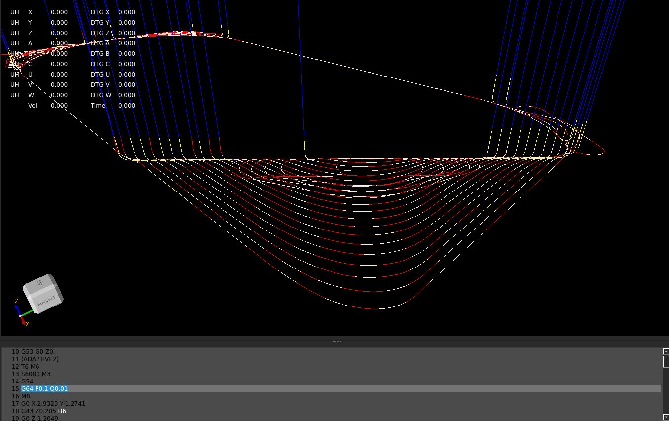
Working on the toolpath blending algoritme.
It's using the gcode G64 P.. Q.. values along the gcode file.
Red are the clothoids, valid in a 3d plane.
Yellow are lines, this are invalid clothoid solutions, out of plane, that we have to port to a spline fillet tomorrow, as
alternative fillet solution.
The settings for G64 used : P0.1 Q0.01
Where P=deviation, creates the fillet.
Where Q=tollerance, filters out only line segments.
// Results of this optimalisation test:
items before G64 P.. Q.. :1214 after:1330 diff:-116
Please Log in or Create an account to join the conversation.
- Grotius
-

- Offline
- Platinum Member
-

- Posts: 2419
- Thank you received: 2345
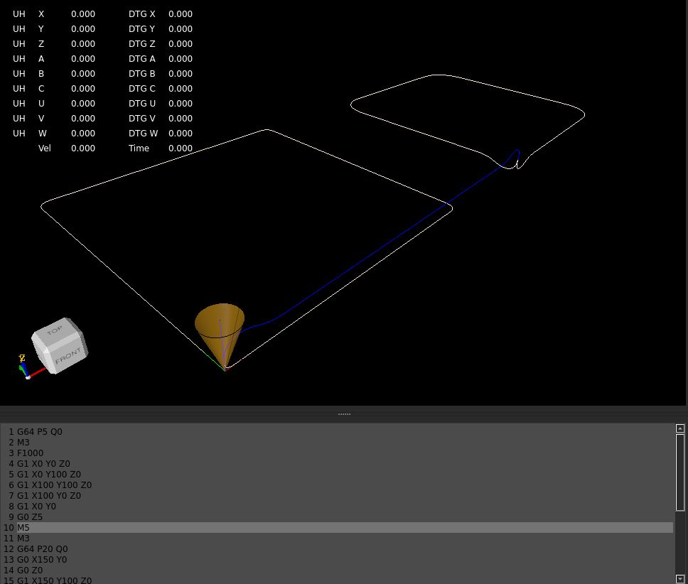
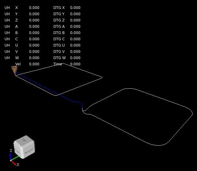
The spline fillets are working. These are used when clothoid fillet fails.
Tested multiple G64 P.. inputs along a gcode file.
The first square is original a G64 P0 with sharp edges.
The first G64 P5 creates ~5mm fillets along the path of the square shape.
Then the second square, the P20 creates ~20mm fillets along path of the second square shape.
The fillets are of type clothoid. Then there are rapid clothoids and feed clothoids, This is important to notice
to do look ahead and optimize speeds further on.
codeberg.org/skynet/hal-core
Attachments:
Please Log in or Create an account to join the conversation.
- Aciera
-

- Offline
- Administrator
-

- Posts: 4624
- Thank you received: 2046
user@debian:~$ sudo apt install libc6
Reading package lists... Done
Building dependency tree... Done
Reading state information... Done
libc6 is already the newest version (2.36-9+deb12u7).
0 upgraded, 0 newly installed, 0 to remove and 0 not upgraded.Please Log in or Create an account to join the conversation.
- Grotius
-

- Offline
- Platinum Member
-

- Posts: 2419
- Thank you received: 2345
Hmm, I will take a look when time comes.
Currently working on the look ahead function to calculate optimal trajectory speeds.
The trajectory consists of lines, arc's, helix, clothoids, & splines.
The max speeds depends on the min,max curvature value of the shape.
- For a clothoid we retrieved the clothoid curvature extrema. "kmin, kmax also know as a kappa value." from the library g2solve3arc.curvature_min_max(..)
- For a arc we can calculate the constant curvature "1/radius" as for a line the curvature=0.
- For the 3-degree spline we calculated curvature min,max using the opencascade GeomLProp_CLProps class.
Then using a optimal angular speed, we can calculate the max speeds for the shapes.
We use a forward sweep over the trajectory followed by a backward sweep over the trajectory between
the rapids. Then the vo, ve is calculated given by a max vm of that segment.
Then there might be a problem when one segment is very long and has high curvature value at one spot.
This then will reduce the overall segment speed. How to deal with this?
Please Log in or Create an account to join the conversation.
- Aciera
-

- Offline
- Administrator
-

- Posts: 4624
- Thank you received: 2046
Then there might be a problem when one segment is very long and has high curvature value at one spot.
This then will reduce the overall segment speed. How to deal with this?
I don't see another way than to limit the speed to the highest curvature value but since this will only apply to fillets I don't think the segments are going to be very long in the first place. Not really sure about this but creating a path deviation of a couple of mm is likely already the limit of what you would want even in a roughing cycle.
Please Log in or Create an account to join the conversation.
- Grotius
-

- Offline
- Platinum Member
-

- Posts: 2419
- Thank you received: 2345
I don't see another way than to limit the speed to the highest curvature
When only dealing with lines and arc's this should be fine.
Once we have spline's and clothoid's the curvature varies along the path.
Say for each segment we create a scurve velocity profile using 5 waypoints.
Then using a B-spline to represent the upper bound of an S-curve profile can be a practical approach.
Then running realtime we are able to follow the upper bound (spline) with the scurve algo along the path.
Then when we for example should apply a spline roughing algo like seen in the science papers,
this then results in perfect velocity changes along the path. A sort of dynamic feed flow. I dont know how to call it.
This upper bound (spline) then also smoothes the transition's between lines and arc's with clothoid fillet in between.
In fact we could create one upper bound (spline) along the entire gcode path. I could test this with a large file.
// Notes:
// curvature = k;
// k = 1 / radius ( this is for arc, or circle, for spline or clothoid use library functions ).
// linear_acc = r * angular_acc
// angular_acc = linear_acc / r
// velocity = sqrt( angular_acc / k )
Please Log in or Create an account to join the conversation.
- Grotius
-

- Offline
- Platinum Member
-

- Posts: 2419
- Thank you received: 2345
For every gcode segment, we calculated the velmax "vm" for the segment given the curvature extrema of
that segment. The curvature extrema is retrieved by c++ functions that iterate over a spline, clothoid curvature.
For arc & line, the curvature is constant and easyer to retrieve.
If you look at the results, i think they aren't shocking or out of scope. My first impression is ok for the vm values.
get vm, g_id:1 radius:0 kmax:0 vm:250
get vm, g_id:9 radius:3.61821 kmax:0.276379 vm:25.1632
get vm, g_id:1 radius:0 kmax:0 vm:250
get vm, g_id:9 radius:3.61821 kmax:0.276379 vm:25.1632
get vm, g_id:1 radius:0 kmax:0 vm:250
get vm, g_id:9 radius:3.61821 kmax:0.276379 vm:25.1632
get vm, g_id:1 radius:0 kmax:0 vm:250
get vm, g_id:9 radius:1.45241 kmax:0.688511 vm:15.9428
get vm, g_id:0 radius:0 kmax:0 vm:250
get vm, g_id:9 radius:3.47639 kmax:0.287654 vm:24.6651
get vm, g_id:0 radius:0 kmax:0 vm:250
get vm, g_id:9 radius:3.47639 kmax:0.287654 vm:24.6651
get vm, g_id:0 radius:0 kmax:0 vm:250
get vm, g_id:9 radius:3.47639 kmax:0.287654 vm:24.6651
get vm, g_id:1 radius:0 kmax:0 vm:250
get vm, g_id:9 radius:14.4729 kmax:0.0690948 vm:50.3264
get vm, g_id:1 radius:0 kmax:0 vm:250
get vm, g_id:9 radius:14.4729 kmax:0.0690948 vm:50.3264
get vm, g_id:1 radius:0 kmax:0 vm:250
get vm, g_id:9 radius:14.4729 kmax:0.0690948 vm:50.3264
get vm, g_id:1 radius:0 kmax:0 vm:250
get vm, g_id:9 radius:3.47639 kmax:0.287654 vm:24.6651
get vm, g_id:0 radius:0 kmax:0 vm:250
get vm, g_id:9 radius:3.47639 kmax:0.287654 vm:24.6651
get vm, g_id:0 radius:0 kmax:0 vm:250
get vm, g_id:9 radius:3.47639 kmax:0.287654 vm:24.6651
get vm, g_id:0 radius:0 kmax:0 vm:250
items G64 P.. Q.. before:22 after:33 diff:-11
From here we can do the look ahead function.
Attachments:
Please Log in or Create an account to join the conversation.
- Aciera
-

- Offline
- Administrator
-

- Posts: 4624
- Thank you received: 2046
Attachments:
Please Log in or Create an account to join the conversation.
- Lcvette
-

- Offline
- Platinum Member
-

- Posts: 1536
- Thank you received: 726
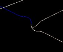
are the two drawn squares of the same code with different trajectory plan methods applied? if so, then I am wrestling with two thought trains.Looks like there is a bit of a problem there:
I don't quite understand why the fillets go above the G0 and below the G1 moves.
The first is me thinking that the Z start/end threashholds should NOT be violated as i could see that being problematic and arbitrarily gouging into parts when repositioning and increasing the cut loads beyond he commanded settings.
The second is that it is really not any different than the way i currently plan the tool paths when roughing and setting smoothing tolerance and stock to leave in the XY cut plane. That said, i do notice that in cam the z heights do not violate the set bottom height of the selected geometry regardless of the smoothing and or tolerance settings. if linuxcnc currently does have not seen evidence of it. of course i typically set the smoothing values in LCNC fairly low, typically not more than 1-3 thousandths so would be difficult to see that when using a stock to leave with enough cushion for it not to show up on the finished part after finish passes are complete.
interesting situation, i am curious to hear more on it from Grotius.
As always, Thank you for the awesome work and effort on this amazing project!
Chris
Please Log in or Create an account to join the conversation.
- Lcvette
-

- Offline
- Platinum Member
-

- Posts: 1536
- Thank you received: 726
unless the minimum radius setting would not allow for the transition to move from the previous line plane to the new line target plane maybe?Looks like there is a bit of a problem there:
I don't quite understand why the fillets go above the G0 and below the G1 moves.
Please Log in or Create an account to join the conversation.


