Trajectory Planner using Ruckig Lib
- ihavenofish
- Offline
- Platinum Member
-

- Posts: 966
- Thank you received: 255
Both fanuc and siemens fit splines for high speed motion. We definitely don't need the g code to describe a spline, but it does often get used under the hood to help describe all the pointes BETWEEN your g1 end points.
Please Log in or Create an account to join the conversation.
- Grotius
-

- Offline
- Platinum Member
-

- Posts: 2419
- Thank you received: 2345
I'm afraid I can't help you with implementing the linked 3d clothoid algorithm.
I have used chat_pdf ai yesterday. This works quite good, but stops and ask's money.
However i don't understand in the page at section (23)
There is a text :
i=1,2;
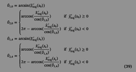
for j=0,1,2,3,4 are the knots of the spline, this i understand. But do you get what i does?
Thanks.
@IhaveNoFish,
get used under the hood
Indeed.
Please Log in or Create an account to join the conversation.
- Aciera
-

- Offline
- Administrator
-

- Posts: 4648
- Thank you received: 2068
Yes. What I meant is that nobody uses splines in the Gcode they load into the controller and thus the spline-related Gcodes implemented in LinuxCNC (ie G5, G5.1, G5.2, G5.3) have really been a solution looking for a problem. That is why I say that they are pretty much useless, _unless_ the can be repurposed for something new like internal path blending.Both fanuc and siemens fit splines for high speed motion
Please Log in or Create an account to join the conversation.
- Aciera
-

- Offline
- Administrator
-

- Posts: 4648
- Thank you received: 2068
I haven't really looked at the paper closely but here is what I think:There is a text :
i=1,2;
for j=0,1,2,3,4 are the knots of the spline, this i understand. But do you get what i does?
If you look at formula (14) you see that the 3d clothoid has two sets (i=1,2) of four parameters (theta, kappa, c , gamma). So 'i' stands for which set of parameters we are looking at.
Please Log in or Create an account to join the conversation.
- Grotius
-

- Offline
- Platinum Member
-

- Posts: 2419
- Thank you received: 2345
This is one of the first formula's to actually solve the clothoid spline.
It looks like 1.0 is for z trajects. Then the zero is knot zero. Begin of spline.
It looks like 2.0 is for xy trajects.
It looks like 1.4 is for z trajects. Then the 4 is knot four. End of spline.
It looks like 2.4 is for xy trajects.
Then you can say i=1, j=2. You have a set for z values, and a set for xy values. Because curvature is not only
on xy plane but also in xz plane.
I still don't fully understand the first formula, the short one at the top.
I think its calculating the "angle start" parameter for the z component.
Attachments:
Please Log in or Create an account to join the conversation.
- Aciera
-

- Offline
- Administrator
-

- Posts: 4648
- Thank you received: 2068
Yes, that is how I understand it.
It looks like 1.0 is for z trajects. Then the zero is knot zero. Begin of spline.
It looks like 2.0 is for xy trajects.
It looks like 1.4 is for z trajects. Then the 4 is knot four. End of spline.
It looks like 2.4 is for xy trajects.
I would sayThen you can say i=1, j=2. You have a set for z values, and a set for xy values. Because curvature is not only on xy plane but also in xz plane.
i=1 is the parameter set for the xz-plane
i=2 is the parameter set for the xy-plane
As for the actual formula I'll need to have a look tomorrow as I have run out of time for today.
Overall the paper seems like quite a thorough step by step presentation of the method which makes me feel somewhat optimistic.
Please Log in or Create an account to join the conversation.
- ihavenofish
- Offline
- Platinum Member
-

- Posts: 966
- Thank you received: 255
back when machines had no memory things were different. my Maho had all sorts of interesting canned cycles for complex motion that you would not have the memory to hold in a program.
Please Log in or Create an account to join the conversation.
- Aciera
-

- Offline
- Administrator
-

- Posts: 4648
- Thank you received: 2068
I still don't fully understand the first formula, the short one at the top.
I think its calculating the "angle start" parameter for the z component.
This calculates the tangent angle (in the XZ plane) in the starting point (s0) of the clothoid on the first trajectory segment after rotating and translating the space corner so that the normal vector of the corner coincides with the z-axis (as shown in Fig 6 ).
If the corner is planar then the expression inside the bracket is zero and Theta(1,0) is zero (ie the tangent is horizontal).
I haven't yet been able to make up my mind if this method can also work for arc-helix corners.
[edit]
Well, I've given it a fair bit of thought and I cannot see a reason why it shouldn't work with helical segments.
Please Log in or Create an account to join the conversation.
- Grotius
-

- Offline
- Platinum Member
-

- Posts: 2419
- Thank you received: 2345
Well, I've given it a fair bit of thought and I cannot see a reason why it shouldn't work with helical segments.
Indeed, this works with anything.
Maybe, maybe we are lucky. In this thread it is possible they will give us 3d clothoid code from Italy university first hand.
He is not looking dayly here, but we have time.
It's also possible to request other 3d clothoid code from China.
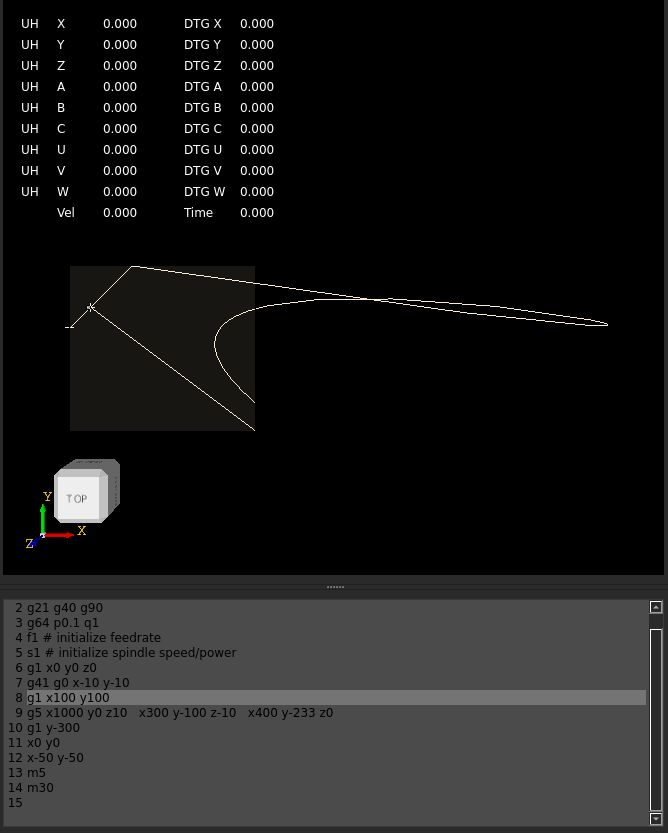
Today i did review the gcode parser source code as i was not satisfied with it. I had problems changing from G40 to G41 after
one line of gcode during the program run. So the tool was not reacting to the given offset side.
So now that is solved. The parser can now read more gcode's at one line. Also it can read the spline
with multi xyz inputs at the same line. It will create xyz point sets.
valid input for spline :
g1 x0 y0 z0
g5 x1 x10 y5 x15 z20
will create spline points :
x0 y0 z0
x1
x10 y5
x15 z20
parser_to_shapes , wich is improved to work better now.
Attachments:
Please Log in or Create an account to join the conversation.
- Aciera
-

- Offline
- Administrator
-

- Posts: 4648
- Thank you received: 2068
Phew, one can sure tell that the paper linked in that thread comes from mathematicians. I could _probably_ workout the other paper written by engineers but this one I don't even need to try. I guess we'll see if they come up with anything useful.Maybe, maybe we are lucky. In this thread it is possible they will give us 3d clothoid code from Italy university first hand.
So if I understand you correctly you are planning on approximating the 3d clothoid fillets with the G5 spline gcode?Also it can read the spline with multi xyz inputs at the same line. It will create xyz point sets.
Please Log in or Create an account to join the conversation.


