Trajectory Planner using Ruckig Lib
- Aciera
-

- Offline
- Administrator
-

- Posts: 4741
- Thank you received: 2125
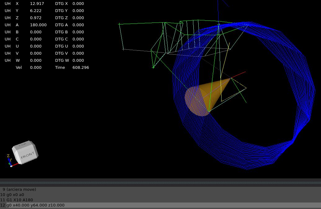
We where wrong about connecting the ta knots with lines.
Yes, it's kind of obvious now that I see it:
If we are at X0 A0 and we have a move G1 X10 A180 then the connecting orientation line will actually intersect the toolpath. l didn't think of that.
I think we need to create the recordedb blue toolpath before program starts. Then create the fillets, like
sketched in the image.
I agree.
But i think it's stupid to use no G2, G3 in 5 axis machine code.
Well, it can't be that stupid if the big players do it that way.
[edit]
BTW, also see the gcode posted in here (not a single arc move):
forum.linuxcnc.org/38-general-linuxcnc-q...lib?start=430#303983
[/edit]
But in any case, ABC path smoothing is not limited to 5axis machining. Which is why I'm not suggesting to tailor this to vector format gcode exclusively. It just seems to be something that could be an option because it's actually the easier case.
For now to keep it simple..
Let's say we stick to the 6 axis machine configuration for now to solve the toolpath & tooldir optimalisation.
Then if this works, we can expand the code with different kinematic models.
Absolutely, pick a kinematic and test it. No point in getting spread out too much.
Please Log in or Create an account to join the conversation.
- Grotius
-

- Offline
- Platinum Member
-

- Posts: 2419
- Thank you received: 2348
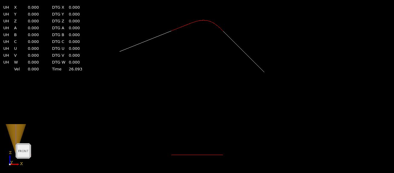
Then we turn 180 radians.
When we turn pi radians, 180 degrees this happens :
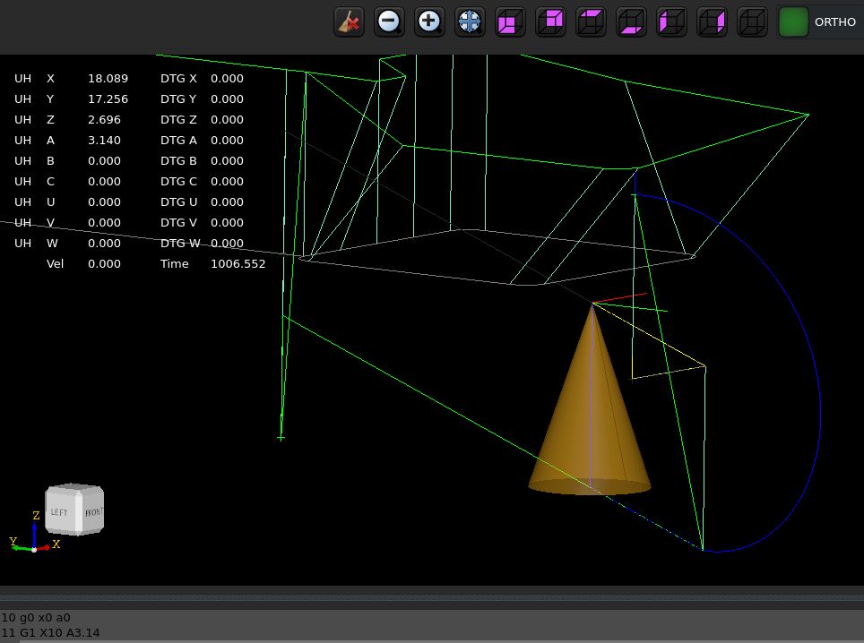
Now the program loads showing the actual tool dir path.
This tool dir path is calculated at program load at the user side. Kernel isn't aware of this.
The toolpath segments are off type 3d_polyline. This is like a linestrip.
This looks like a nice basis to create fillets for both the tcp path & tooldir path.
Attachments:
Please Log in or Create an account to join the conversation.
- Aciera
-
- Offline
- Administrator
-
- Posts: 4741
- Thank you received: 2125
I agree.This looks like a nice basis to create fillets for both the tcp path & tooldir path.
Please Log in or Create an account to join the conversation.
- Grotius
-
- Offline
- Platinum Member
-
- Posts: 2419
- Thank you received: 2348
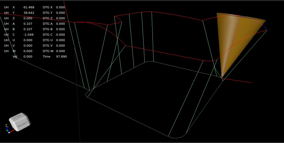
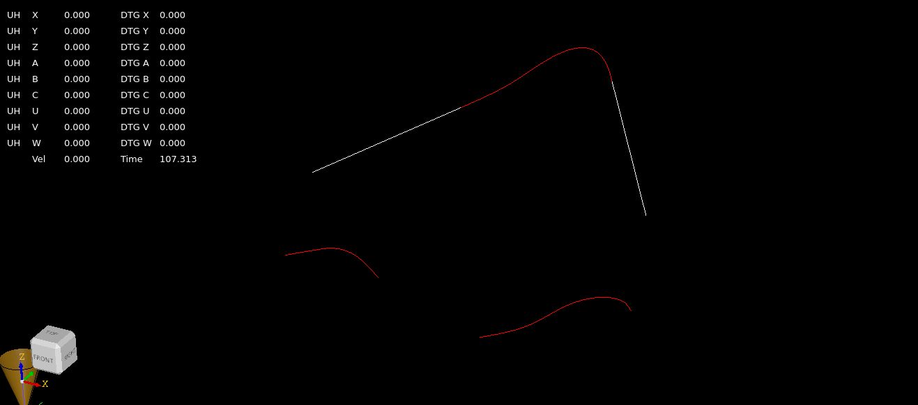
On the picture we have a big problem, the 2 thick blue lines, these segments are connected non-planar.
The clothoids library works for connecting segments that can create a plane.
This situation can not create a plane, or at least the 2 connected segments are not on the same plane.

In a quite moment i thought about this problem yesterday.
The clothoids are valid as they can be on a 3d plane.
So this is not valid to construct a clothoid fillet. How to go on?
What we acutally needed is a 3d spline or a 3d clothoid wich is valid non planar.
For the 3d spline, this can be a problem if you have 30+ waypoints. Spline with 30 degree or more are in my view useless and
often they break on the algo.
So my solution was to think about a 3d clothoid creation wich is valid non planar.
The idea i got was to construct & project 2 clothoids each on a plane.
First clothoid projects on the xy plane, given the 2 3d lines. This one don't use the z component.
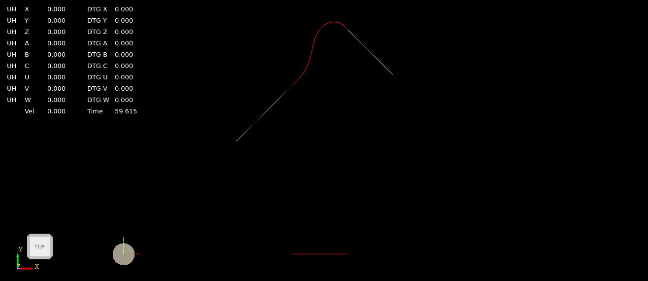
Second clothoid projects on the xz plane, given the 2 3d lines. This one don't use the y component.
Then interpolate the first clothoid in time from t=0-1.
Then for the t, find the x value of the second clothoid, then use the z value as solution for the interpolated point.
Here is a video how it works :
Now one thing to do is when the first clothoid has no x value, but has y value, use this then.
What do you think about the result?

Attachments:
Please Log in or Create an account to join the conversation.
- Aciera
-
- Offline
- Administrator
-
- Posts: 4741
- Thank you received: 2125
I wonder if it were easier to project the two segments (ie the two thick blue arcs) onto the plane defined by the tool orientation vector that passes through the intersection point. How difficult would it be for your algo to calculate the plane defined by a vector and it's corresponding TA/TO knot and then do the projection? Is that possible at all?
Please Log in or Create an account to join the conversation.
- Grotius
-
- Offline
- Platinum Member
-
- Posts: 2419
- Thank you received: 2348
That's not difficult to do, opencascade is good in vectors, planes, etc.
But then still if a or b rotates below the workpiece in one gcode line, we are lost.
The 3d clothoid works, but output is not alway's valid. So i have to review my approach.
Sheisse.
Please Log in or Create an account to join the conversation.
- Aciera
-
- Offline
- Administrator
-
- Posts: 4741
- Thank you received: 2125
Just so I understand the requirements for the clothoids library:But then still if a or b rotates below the workpiece in one gcode line, we are lost.
I presume that can be any plane in space (ie it does not have to be XY XZ or YZ)?The clothoids library works for connecting segments that can create a plane.
If that is correct we can use the plane that is defined by the tool orientation vector and the corresponding point (TA knot) and project the two TA line segments (ie the one that comes from the previous TA knot and the one that goes to the next TA knot) onto that plane. Then we have the projected lines on a common plane and we can use the clothoids library to create a G2 continuous fillet.
Of course we would need to do this for all TA knots and their respective planes in space.
[edit]
Ok, I think we can forget this idea as this will still not create 3D clothoid curves but only 2D.
[/edit]
Please Log in or Create an account to join the conversation.
- Aciera
-
- Offline
- Administrator
-
- Posts: 4741
- Thank you received: 2125
How do you handle line-3d_arc segment corners in tool paths?
Please Log in or Create an account to join the conversation.
- Aciera
-
- Offline
- Administrator
-
- Posts: 4741
- Thank you received: 2125
With this approach there would only be line-line segment corners.
Please Log in or Create an account to join the conversation.
- Grotius
-
- Offline
- Platinum Member
-
- Posts: 2419
- Thank you received: 2348
Yes, any plane.
If that is correct we can use the plane that is defined by the tool orientation vector and the corresponding point (TA knot) and project the two TA line segments (ie the one that comes from the previous TA knot and the one that goes to the next TA knot) onto that plane. Then we have the projected lines on a common plane and we can use the clothoids library to create a G2 continuous fillet.
Of course we would need to do this for all TA knots and their respective planes in space.
Yes that is correct. Three ta knot's can create a plane. On this plane we could record the tcp-ta intersection along the plane.
Maybe this is the best solution, we have to test it i think.
[edit]
Ok, I think we can forget this idea as this will still not create 3D clothoid curves but only 2D.
[/edit]
It will create a 2d clothoid in 3d space, it's valid as long it draw's the clothoid on a 3d plane with the current clothoid lib as is.
Isn't this the same situation as you would have when adding a fillet between a straight line segment and a helix segment in Gcode (except of course the helix segment would be oriented to XY, XZ or YZ plane)?
For now it isn't valid to create clothoid fillet on a helix. I didn't told it yet. It would be valid if clothoid is 3d.
It would be valid if fillet is of type 3d spline.
How do you handle line-3d_arc segment corners in tool paths?
I think you mean, for using clothoids valid combinations are line-arc, arc-line, arc-arc as long as they are on the same plane.
If the clothoid library can only create 2d curves then the only solution I see would be to approximate all arcs with a polyline. Which is exactly what 5axis CAM output seems to do.
With this approach there would only be line-line segment corners.
The situation we have now is a 3d arc to 3d arc connection, both arc's are on exotic plane position. non xy,xz etc.
So this would not happen in normal gcode. This happens because we have a tooldir path recorded.
For normal gcode, i think the clothoid can cover 95%-100% of the fillets.
Things left to investegate:
1. We can test your plane idea using the 2 ta knots as plane.
2. We can test using 3d spline fillets, for our tooldir path.
3. We can invest more time in creating 3d clothoids to cover all exeptions.
Please Log in or Create an account to join the conversation.