Trajectory Planner using Ruckig Lib
- Aciera
-

- Offline
- Administrator
-

- Posts: 4755
- Thank you received: 2135
If you want to handle the specific kinematics separately then maybe it would be more generic to calculate smoothed tool orientation as a unit vector (ie length = 1) with origin at (x,y,z)=(0,0,0).Yes XYZAC, XYZBC need different kinematics. For the math and calculating the tool direction in opencascade i just
thought use the letters A & B. At this stage the kinematics are not solved. Only the tool tcp & tool direction is then solved.
Do you think this is ok?
1. Calculate the vector pointing from smooth TCP knot to smooth TA/TO knot
2. Translate this vector to (x,y,z)= (0,0,0,) (ie subtract smooth TCP knot coordinates from start and end points)
3. Normalize the vector to get a length of 1.
To get the specific tool orientation angles we could parse the ini file to find out which rotary joints are available and calculate the appropriate angles (ie A,B or C ) from this orientation vector using 'atan2' function. I have done some work that calculates spindle rotary orientations from a given tool orientation vector, although that was in python. There will likely be some issues with rotation directions and joint limits that I had to deal with but if your algo spits out the orientation as a vector then this could all be handled separately.
Please Log in or Create an account to join the conversation.
- Grotius
-

- Offline
- Platinum Member
-

- Posts: 2419
- Thank you received: 2348
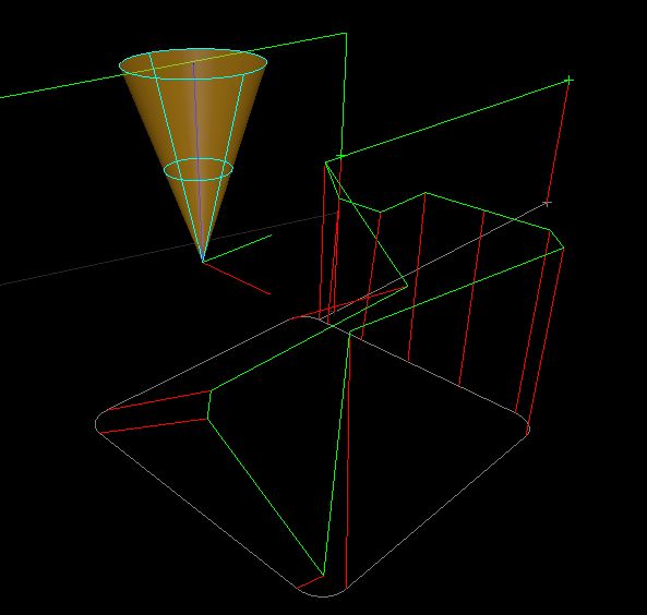
I just made a test for 5 axis. xyz abc.
Where a rotates around x, b rotates around y. The c axis is the cone symetric axis, like spindle orientation.
The tool direction line is 15mm of lenght.
Please Log in or Create an account to join the conversation.
- Aciera
-
- Offline
- Administrator
-
- Posts: 4755
- Thank you received: 2135
I like the added preview of the tool orientation.
Please Log in or Create an account to join the conversation.
- Aciera
-
- Offline
- Administrator
-
- Posts: 4755
- Thank you received: 2135
Which reminds me that to calculate the tool orientation vector correctly we already need to know the kinematic for which the GCode was created. In your example the C axis value does not have any effect on the orientation tool path at all because it is applied last. If, however, the C axis was applied first (ie it would be the primary rotary axis) the path would look much different.Where a rotates around x, b rotates around y. The c axis is the cone symetric axis, like spindle orientation.
Hence we will need a way to encode the general type of kinematic in the ini file. We need to know whether the rotary axis is moving the tool or the work and if the rotations are on the same side (tool / work) the we need to know which is the primary and which is the secondary.
I assume there are economic software functions available to apply rotations to a given vector in any sequence?
Please Log in or Create an account to join the conversation.
- Aciera
-
- Offline
- Administrator
-
- Posts: 4755
- Thank you received: 2135
[edit]
www.fanucamerica.com/CMSMedia/DnP/Vector...e%20Machining_11.pdf
Please Log in or Create an account to join the conversation.
- Grotius
-
- Offline
- Platinum Member
-
- Posts: 2419
- Thank you received: 2348
From the document i found interesting line :
G1 X0 Y0 Z0 I-0.5 J0.5
K0.7071. For a properly defined vector
They use I,J,K for vector. But for G2, G3 that is not a valid gcode input. Preferr to use AB for the vector and use
C for the spindle orientation.
--
Basicly when using external rotary table, we could use this as axis u,v,w.
Where u=rotation around x, v=rotation around y, and w=rotary table clamp symetric axis.
Then we have a xyz, abc, uvw machine, 6 axis for tool, 3 axis for extern rotary table.
But this then is a single machine config that has valid kinematics for a few configurations like : xyz router,
xyz router + abc head. xyz router + abc head and a uvw rotary table.
So all other configurations, like xyzab, xyzac, xyza, etc need a different software approach.
And i think not all of these variants can use tooldirection optimalisation. Like xyza, where a is secondaire z axis.
So if i add selectors to the program config section :
1. xyzab
2. xyabc
3. xyz
4. xyza
5 xyzabc
6 xyzabcuvw
Then it should use correspondenting c++ function to translate gcode into the proper tcp, and other axis.
Like choosing kinematics.
What you think?
Please Log in or Create an account to join the conversation.
- Aciera
-
- Offline
- Administrator
-
- Posts: 4755
- Thank you received: 2135
Yes, that is because the 5axis CAM output only consists of straight line segments (ie no G02 or G03 commands) the CAM user defines the length of the line segments.They use I,J,K for vector. But for G2, G3 that is not a valid gcode input.
I'm not suggesting to limit the interpreter to this format but it would make a lot of sense to allow vector format as an option since it makes the calculation of the tool vector unnecessary. It seems kind of silly to have the CAM calculate the tool vector and then to invest in a postprocessor to calculate the rotary angles from the tool vector just to have your algorithm reconstruct the tool vector that we already had in the CAM output.
So basically:
1. Check if the first G01 command has I,J,K words
2a. if no then read the machine kinematics from the ini file and recalculate the tool vector from the ABC values
2b. if yes, use the IJK values to create the tool vector directly.
Not sure I can follow you there. I don't see the need for U,V,W for work side rotations. Come to think of it I may have been confused myself by thinking we need to handle work side rotation differently from tool side rotation as I thought we would need to reverse the rotation direction. However the positive rotation is defined in respect to the tool rotation around the machine XYZ in either case.Basicly when using external rotary table, we could use this as axis u,v,w.
Where u=rotation around x, v=rotation around y, and w=rotary table clamp symetric axis.
Then we have a xyz, abc, uvw machine, 6 axis for tool, 3 axis for extern rotary table.
I have created kinematic models with mixed work side and tool side rotations but my 'tilted work plane work' only dealt with machines with tool side rotation (primary C, secondary B or A). Maybe I'll find some time to expand on that.
So all other configurations, like xyzab, xyzac, xyza, etc need a different software approach.
And i think not all of these variants can use tooldirection optimalisation. Like xyza, where a is secondaire z axis.
For Gcode that was postprocessed to fit a specific kinematic you need to account for the kinematic settings in the postprocessor (PP) to basically undo what the PP did AND you need to know the machine kinematics for the calculation of the rotary axis position to achieve the requested tool orientation.
If you decide to allow vector format Gcode then you only need to worry about kinematics for the calculation of the rotary axis position to achieve the requested tool orientation. This is why I suggested looking at vector (ie IJK) format as it's really the easier task.
However, the usual 4axis case will still likely still involve XYZA gcode. I think this would still work with the orientation path smoothing as it still creates a valid 3d curve that can be smoothed out to a G2 continuous path. What happens if you feed your 5axis test a XYZA gcode (ie B and C angle values all zero)?
Note: I would interpret XYZA as a machine with linear cartesian XYZ axes and a rotary A (ie rotates the tool around the X axis). And again I _think_ that it is irrelevant whether A rotates the work or the tool.
Overall the current use of kinematic modules works quite well, except for the inability of the trajectory planner to catch axis limit violations in the look ahead and decelerate in a controlled manner before raising a sudden joint limit abort. This would be nice to have but would mean that the planner passes every motion segment through the custom kinematic module to check for limit violations before actually adding it to the queue.Then it should use correspondenting c++ function to translate gcode into the proper tcp, and other axis.
Like choosing kinematics.
Please Log in or Create an account to join the conversation.
- Aciera
-
- Offline
- Administrator
-
- Posts: 4755
- Thank you received: 2135
forum.linuxcnc.org/10-advanced-configura...gcode?start=0#143455
As for the absence of arc moves in vector format code see this post in the same thread:
forum.linuxcnc.org/10-advanced-configura...gcode?start=0#143507
Please Log in or Create an account to join the conversation.
- Grotius
-
- Offline
- Platinum Member
-
- Posts: 2419
- Thank you received: 2348
Yes, that is because the 5axis CAM output only consists of straight line segments (ie no G02 or G03 commands) the CAM user defines the length of the line segments.
I wasn't aware off this. This makes things easyer.
But i think it's stupid to use no G2, G3 in 5 axis machine code.
--
We where wrong about connecting the ta knots with lines.
Proposing connect ta (tool dir points) knots with lines. :
The thin blue line is the recorded tooldir path:
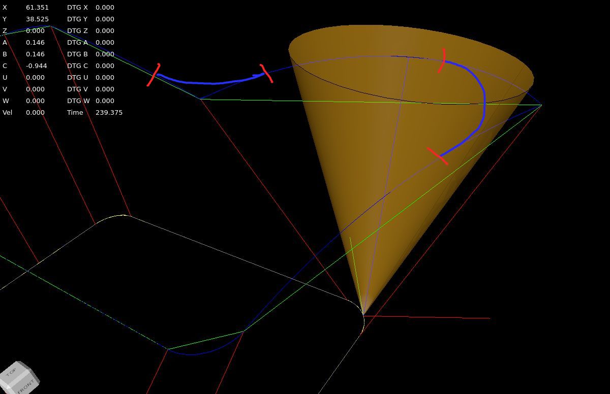
I think we need to create the recordedb blue toolpath before program starts. Then create the fillets, like
sketched in the image.
This example uses gcode with no G64 fillets so far. This is just a example howto get where we want to.
Short movie how to tool tp and tool dir are recorded.
I will now try to create an idea to add clothoid fillets to the tool tp path and tool dir path.
Attachments:
Please Log in or Create an account to join the conversation.
- Grotius
-
- Offline
- Platinum Member
-
- Posts: 2419
- Thank you received: 2348
2a. if no then read the machine kinematics from the ini file and recalculate the tool vector from the ABC values
2b. if yes, use the IJK values to create the tool vector directly.
I think in my program if u have 5 axis gcode as you say that are only G0 or G1 segments.
Then parse I,J,K to letters A,B,C if a line has a G0 or G1. This could be done also by the 5 axis post processor.
The A,B,C are the tool vector. It doen's have to be a normalized vector.
Inside the program A, B, C has a transformation matrix, they are multiplied in order. Then multiplied by a tcp offset matrix.
For now to keep it simple..
Let's say we stick to the 6 axis machine configuration for now to solve the toolpath & tooldir optimalisation.
Then if this works, we can expand the code with different kinematic models.
Please Log in or Create an account to join the conversation.