Trajectory Planner using Ruckig Lib
- Aciera
-

- Offline
- Administrator
-

- Posts: 4755
- Thank you received: 2135
Yes, that is what I'm thinking.If i draw the tool orientation vector lenght:10mm at each gcode line. Or at each known position.
Then i connect these tool orientation's at the top with a poly line.
Then create fillets inbetween the polylines? Then set tool orientation vector to touch the fillets?
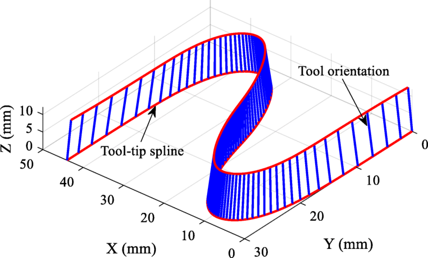
This image is from the preview of the paper linked above. The tool position is the curve in red and the tool orientation is the curve in blue. The blue curve would be the G2 continuous representation of the polyline that connects the green dots marked 'Knot of TA'.

Mind you, I have not really thought about what a particular machine's kinematic restriction will mean when using this approach. If we have a machine with only an A-rotary then we may not be able to orient the physical tool to the calculated (smoothed) 3D angles (ABC).
Attachments:
Please Log in or Create an account to join the conversation.
- Grotius
-

- Offline
- Platinum Member
-

- Posts: 2419
- Thank you received: 2348
I'm still a little confused how to solve this 5 axis geometry. Especially caluclating the inbetween TA knots.
If knot Tcp.0 to Tcp.1 = 100mm.
if knot Ta.0 to Ta.1 = 150mm.
Then tcp 50% = 50mm, then ta=75mm? This should be the interpolation.
Should it be like above?
For only "a" axis, i think just interpolate this. And make it a master move when "a" axis need more time then xyz.
For halcore the progress is running a program with scurve now.
It can start from line, motion fwd, motion reverse. It has a scope for the trajectory planner.
Please Log in or Create an account to join the conversation.
- Aciera
-
- Offline
- Administrator
-
- Posts: 4755
- Thank you received: 2135
say we have a gcode line:I'm still a little confused how to solve this 5 axis geometry. Especially caluclating the inbetween TA knots.
G1 X1 Y2 Z3 A10 C20
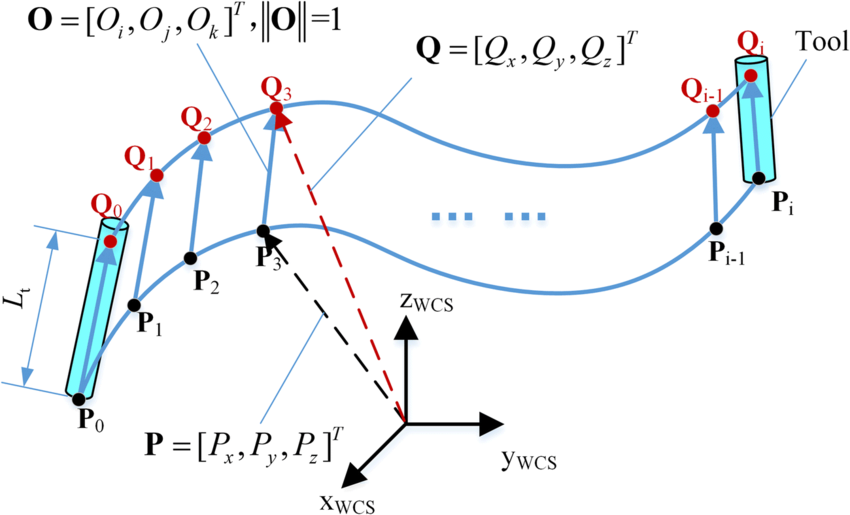
for the end of each segment we have the toolposition (TCP knot in XYZ coordinates) and the tool orientation vector (using the A and C angles in this example or by whatever angle(s) the kinematic for the particular machine uses eg A, AB, BC ..)
The corresponding TA knot is offset from the TCP knot by a fixed distance (say 10mm) along the tool orientation vector.
Please Log in or Create an account to join the conversation.
- Aciera
-
- Offline
- Administrator
-
- Posts: 4755
- Thank you received: 2135

The current tool position XYZ (ie the TCP knot) is at the center of the sphere.
The current tool orientation (black arrow) is defined by angles 'A' and 'C' in red (ie this would be an XYZAC kinematic), the vector points to the corresponding TA knot (green dot, here called 'TO' knot) a certain fixed distance away.
The other two green dots would represent the previous and the next TA/TO knot for the previous and the next TCP knots.
Attachments:
Please Log in or Create an account to join the conversation.
- Aciera
-
- Offline
- Administrator
-
- Posts: 4755
- Thank you received: 2135
Attachments:
Please Log in or Create an account to join the conversation.
- Aciera
-
- Offline
- Administrator
-
- Posts: 4755
- Thank you received: 2135
Attachments:
Please Log in or Create an account to join the conversation.
- Grotius
-
- Offline
- Platinum Member
-
- Posts: 2419
- Thank you received: 2348
I understand now.
Then my interpolation proposal seems correct :
G1 X1 Y2 Z3 A10 C20
G1 X11 Y2 Z3 A20 C40
Here the xyz moves 10 mm = Line lenght xyz.
Lets assume the spline or fillet lenght from "Q0 to Q1" -> "A10 C20 to A20 C40" = 40mm
Then the interpolation for xyz at 5mm = t0.5 (for interpolation i use time 0 to 1 for a segment)
For Q0 to Q1 is t0.5*40mm = 20mm on the spline or fillet path.
Then we can calculate new vector for A & C. This vector then has a A and a C value for radians.
This whole circus can be done offline in opencascade cad.
So just like you proposed, we do the
1. Run the clothoid fillets algo based on G64 P & Q input values. In one gcode file different fillet sizes can be given.
2. Run a tool orientation algo for a & b axis. I think using A & B is simplest. This then solves smoothing for A & B axis toolpath.
3. Run a check if A & C orientation's can be made in the xyz move time, otherwise xyz velocity must be lowered down.
Did we miss something? Or is it ready to be coded?
Please Log in or Create an account to join the conversation.
- Grotius
-
- Offline
- Platinum Member
-
- Posts: 2419
- Thank you received: 2348
Tonight i went to the production machine with a hard-drive for testing hal-core.
After figuring out how to setup hal parport and run posix realtime etc for a few hours,
i managed to run the machine on hal-core.
Most of you know halcore uses no python and is very compact coded.
It run's posix realtime, so i am happy for today.
github up to date
Please Log in or Create an account to join the conversation.
- Aciera
-
- Offline
- Administrator
-
- Posts: 4755
- Thank you received: 2135
This would only work for a machine with XYZAB kinematics so the algorithm needs to be adjusted depending on the type of machine kinematics used in the particular config as solving for AB angles will not work for XYZAC (C axis instead of a B axis) or XYZBC (C axis instead of a A axis) machines.2. Run a tool orientation algo for a & b axis. I think using A & B is simplest. This then solves smoothing for A & B axis toolpath.
I'm still a bit confused seeing that tool motion still decelerates to a full stop after each segment. I guess feed rate blending over consecutive feed moves is a separate problem to solve but given the importance of constant tool velocity in CNC trajectory planning I'm wondering if you have a solution in mind for this yet.Tonight i went to the production machine with a hard-drive for testing hal-core.
After figuring out how to setup hal parport and run posix realtime etc for a few hours,
i managed to run the machine on hal-core.
Please Log in or Create an account to join the conversation.
- Grotius
-
- Offline
- Platinum Member
-
- Posts: 2419
- Thank you received: 2348
Yes XYZAC, XYZBC need different kinematics. For the math and calculating the tool direction in opencascade i just
thought use the letters A & B. At this stage the kinematics are not solved. Only the tool tcp & tool direction is then solved.
Do you think this is ok?
I'm still a bit confused seeing that tool motion still decelerates to a full stop after each segment.
In the video i speak about a first test without any motion logic for hal-core. Stopping motion at each gcode line.
Next step now is to add g64 fillets to the gcode. Then eventually the look ahead add's end velocity where it can.
Please Log in or Create an account to join the conversation.