Trajectory Planner using Ruckig Lib
- hmnijp
- Offline
- Senior Member
-

Less
More
- Posts: 42
- Thank you received: 49
18 Jun 2024 10:23 - 18 Jun 2024 10:35 #303243
by hmnijp
Replied by hmnijp on topic Trajectory Planner using Ruckig Lib
yes, it is a spiral in the corresponding plane (g17 for Z)
Linuxcnc is also able to draw multiturn spirals
G2 or G3 <X- Y- Z- I- J- P-> where P is the number of turns
Full circle or spiral programming is possible without axis words
G2 Z- I- J- P-
Linuxcnc is also able to draw multiturn spirals
G2 or G3 <X- Y- Z- I- J- P-> where P is the number of turns
Full circle or spiral programming is possible without axis words
G2 Z- I- J- P-
Last edit: 18 Jun 2024 10:35 by hmnijp.
The following user(s) said Thank You: Lcvette, Grotius
Please Log in or Create an account to join the conversation.
- Grotius
-

- Offline
- Platinum Member
-

Less
More
- Posts: 2419
- Thank you received: 2348
18 Jun 2024 14:44 #303266
by Grotius
Replied by Grotius on topic Trajectory Planner using Ruckig Lib
@Hmnijp,
Thanks for confirming.
Thanks for confirming.
The following user(s) said Thank You: Lcvette
Please Log in or Create an account to join the conversation.
- Grotius
-
- Offline
- Platinum Member
-
Less
More
- Posts: 2419
- Thank you received: 2348
19 Jun 2024 15:06 #303353
by Grotius
Replied by Grotius on topic Trajectory Planner using Ruckig Lib
Hi,
The helix, or spirals are working now for 3 planes. G17 xy-plane, G18 xz-plane, G19 yz-plane.
They use G2 or G3 for helix direction.
I started using opencascade to create a cilinder surface, and then combine it with a line on that surface,
there was a example, it all turned out to nothing as i need to start at a given point, need to end at a given point,
add extra turns if requested etc.
So ended up starting to write functions plane by plane, as i find the yz-plane the most difficult to code.
And i also seperated G2 and G3 functions to keep it simple.
And as Hmnijp mentioned in his post, it can use the P word for nr of turns.
This nr of turns is tested in the lcnc 3d example ngc file:
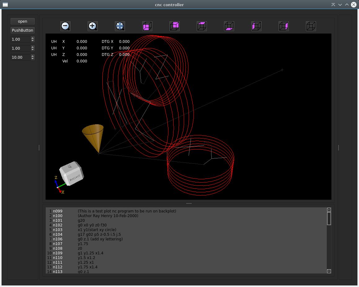
And then the gcode file of robh, the helix is also color red:
Ok, this looks ok for now.
Helix source file creating a spiral, helix : creating a G2 helix
My conclusion is : Helix start, endpoints are impossible to use for a 2d tri-clothoid fillet to get G2 continuity.
The only way to get the G2 continuity fillet for a helix is to modify the helix spring curvature into a tri-clothoid curvature.
So the spring of the helix will have the model of a tri-clothoid. Is this usefull?
The helix, or spirals are working now for 3 planes. G17 xy-plane, G18 xz-plane, G19 yz-plane.
They use G2 or G3 for helix direction.
I started using opencascade to create a cilinder surface, and then combine it with a line on that surface,
there was a example, it all turned out to nothing as i need to start at a given point, need to end at a given point,
add extra turns if requested etc.
So ended up starting to write functions plane by plane, as i find the yz-plane the most difficult to code.
And i also seperated G2 and G3 functions to keep it simple.
And as Hmnijp mentioned in his post, it can use the P word for nr of turns.
This nr of turns is tested in the lcnc 3d example ngc file:
And then the gcode file of robh, the helix is also color red:
Ok, this looks ok for now.
Helix source file creating a spiral, helix : creating a G2 helix
My conclusion is : Helix start, endpoints are impossible to use for a 2d tri-clothoid fillet to get G2 continuity.
The only way to get the G2 continuity fillet for a helix is to modify the helix spring curvature into a tri-clothoid curvature.
So the spring of the helix will have the model of a tri-clothoid. Is this usefull?
Attachments:
The following user(s) said Thank You: tommylight, Lcvette
Please Log in or Create an account to join the conversation.
- Grotius
-
- Offline
- Platinum Member
-
Less
More
- Posts: 2419
- Thank you received: 2348
19 Jun 2024 15:54 #303355
by Grotius
Replied by Grotius on topic Trajectory Planner using Ruckig Lib
Hi,
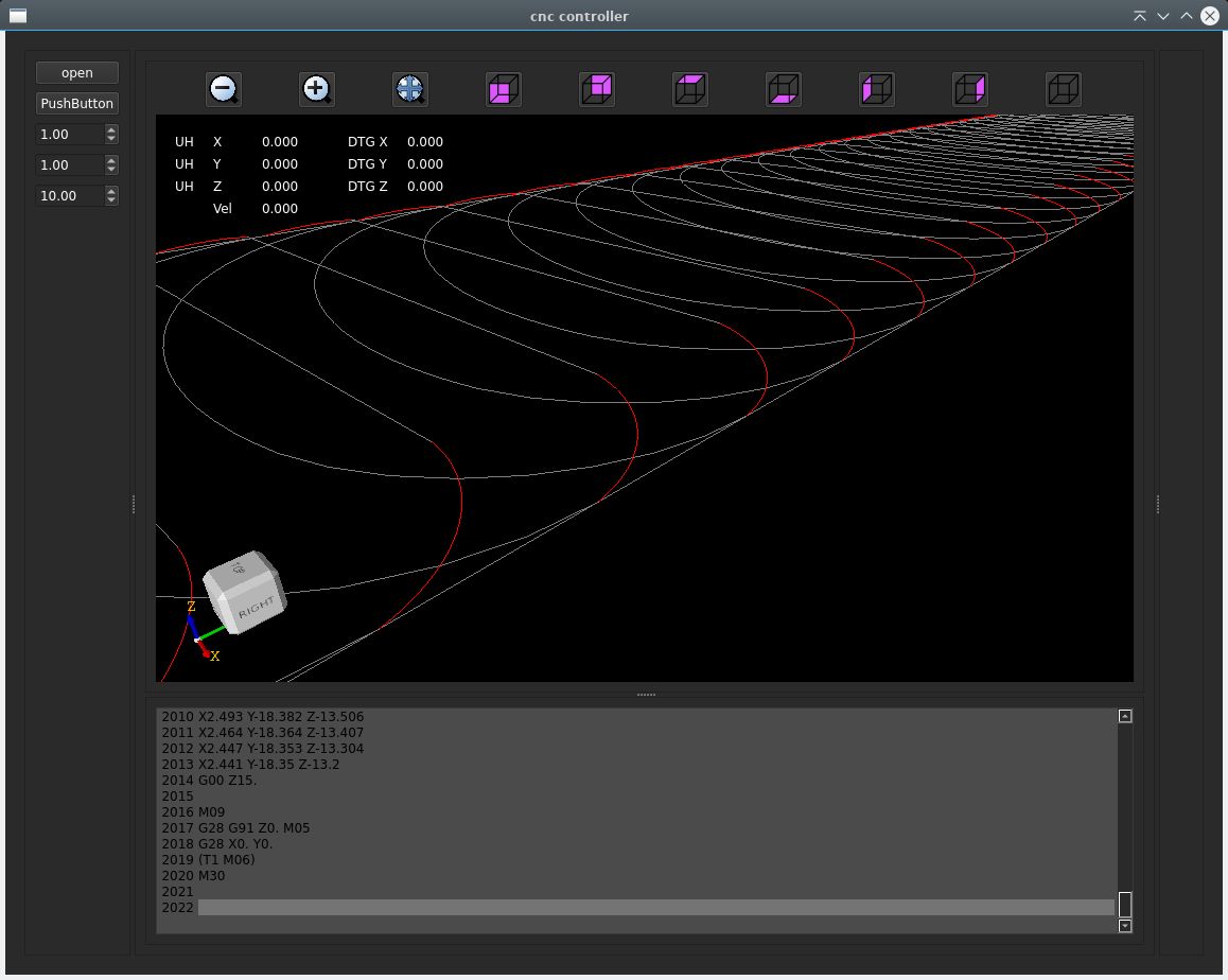
Now i added a helix G2 continuity test function.
Instead of drawing a helix in a plane, we add something special.
It's a G2 helix (clockwise arc), 2 gcode lines are attached. You can see what happens in both situations.
So it starts the helix with zero curvature (k value) in the spring axis, in this case top view xy plane G17.
Then along the path it uses a cos function to increase the curvature along the path.
Then at the end it comes down to zero curvature.
So now this spiral, or helix has G2 continuity and can be used to create fillets with a tri-clothoid.

I think for spiral we can use the gcode L word to enable G2 continuity mode like :
G2 P2 I0.5 J0.5 Z1 L1
P= turns
L= enable G2 continuity for spirals
Now i added a helix G2 continuity test function.
Instead of drawing a helix in a plane, we add something special.
It's a G2 helix (clockwise arc), 2 gcode lines are attached. You can see what happens in both situations.
So it starts the helix with zero curvature (k value) in the spring axis, in this case top view xy plane G17.
Then along the path it uses a cos function to increase the curvature along the path.
Then at the end it comes down to zero curvature.
So now this spiral, or helix has G2 continuity and can be used to create fillets with a tri-clothoid.
I think for spiral we can use the gcode L word to enable G2 continuity mode like :
G2 P2 I0.5 J0.5 Z1 L1
P= turns
L= enable G2 continuity for spirals
Attachments:
The following user(s) said Thank You: Lcvette, Aciera
Please Log in or Create an account to join the conversation.
- automata
- Offline
- Premium Member
-

Less
More
- Posts: 99
- Thank you received: 86
19 Jun 2024 17:16 #303367
by automata
Replied by automata on topic Trajectory Planner using Ruckig Lib
Kudos Grotius!
Maybe the L1 can be made as a G64 parameter and the default value set at startup like the G64 P and Q parameters.
Another option would be to set it up as an ini parameter.
Will the clothoid interpolation work for 9 axis G1 moves?
Regards
automata
Maybe the L1 can be made as a G64 parameter and the default value set at startup like the G64 P and Q parameters.
Another option would be to set it up as an ini parameter.
Will the clothoid interpolation work for 9 axis G1 moves?
Regards
automata
The following user(s) said Thank You: Lcvette, Grotius
Please Log in or Create an account to join the conversation.
- Grotius
-
- Offline
- Platinum Member
-
Less
More
- Posts: 2419
- Thank you received: 2348
19 Jun 2024 18:08 #303373
by Grotius
Replied by Grotius on topic Trajectory Planner using Ruckig Lib
@Automata,
Yes, G64 P.. Q.. L..
Will the clothoid interpolation work for 9 axis G1 moves?
It is going to work, but we need someone who makes a tiny document how the rules are to achieve this.
I mean, i will code it following the document guide lines, coding steps.
So the document needs a few steps, what are the rules for interpolation on 9 axis. Wich axis first, when what
to do and so on.
Maybe you can make the document and think about it extensively.
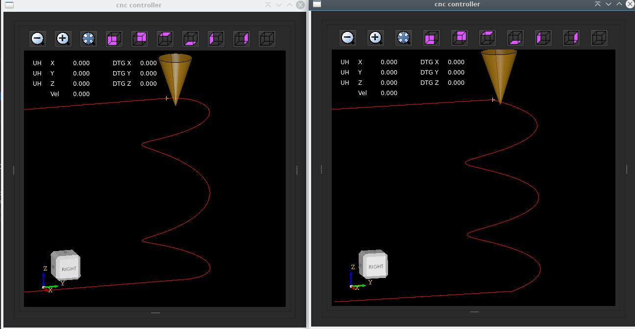
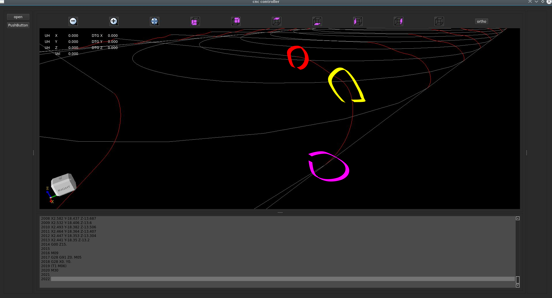
Here are the results of a helix not doing a G2 continuity, G2 ... L0
Clearly you see sharp transition corner in yellow, this is bad for machine :
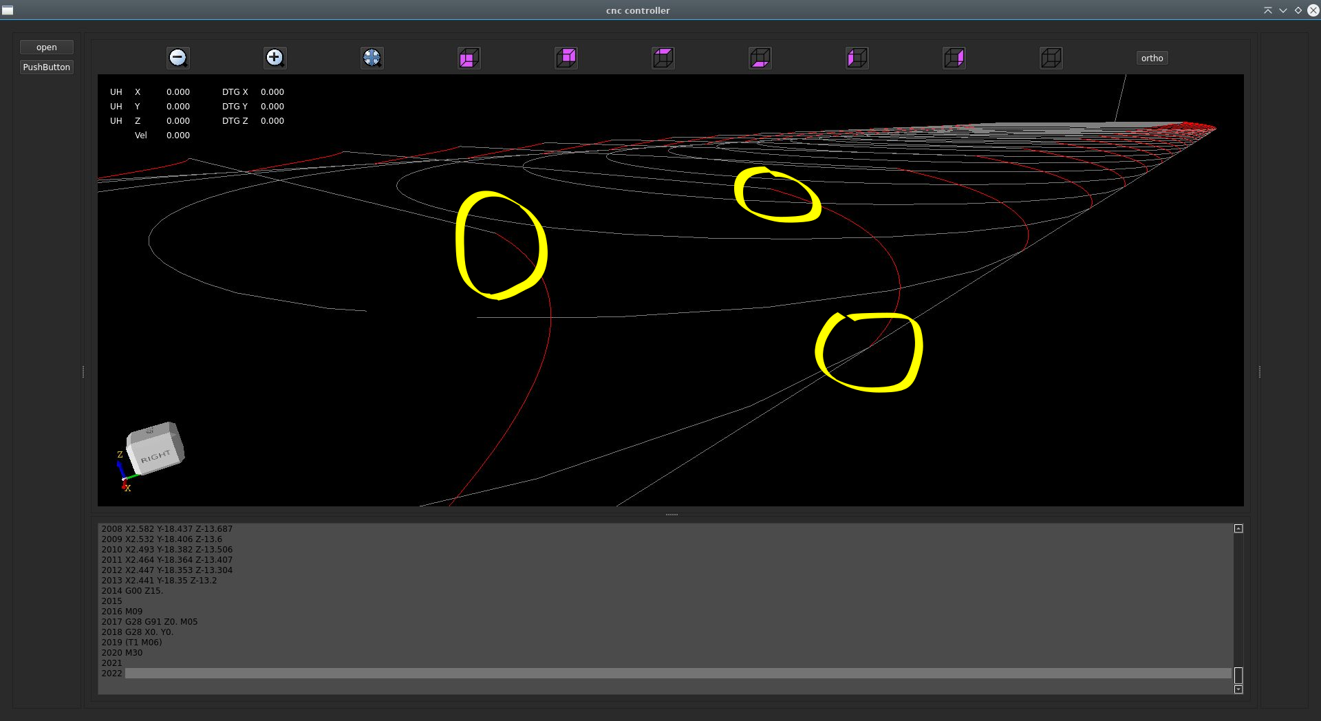
And a helix doing G2 continuity in the testfile of Robh, G2 ... L1:
Yellow is transition from helix to helix. Red and purple, no transition corners visible.
Path is better for machine.
Yes, G64 P.. Q.. L..
Will the clothoid interpolation work for 9 axis G1 moves?
It is going to work, but we need someone who makes a tiny document how the rules are to achieve this.
I mean, i will code it following the document guide lines, coding steps.
So the document needs a few steps, what are the rules for interpolation on 9 axis. Wich axis first, when what
to do and so on.
Maybe you can make the document and think about it extensively.
Here are the results of a helix not doing a G2 continuity, G2 ... L0
Clearly you see sharp transition corner in yellow, this is bad for machine :
And a helix doing G2 continuity in the testfile of Robh, G2 ... L1:
Yellow is transition from helix to helix. Red and purple, no transition corners visible.
Path is better for machine.
Attachments:
The following user(s) said Thank You: pommen, Lcvette
Please Log in or Create an account to join the conversation.
- Becksvill
- Offline
- Elite Member
-

Less
More
- Posts: 206
- Thank you received: 103
21 Jun 2024 21:04 #303514
by Becksvill
Replied by Becksvill on topic Trajectory Planner using Ruckig Lib
We Are about to do a big aluminium 4axis carving and the current trajectory generator swaps to no look ahead when it combines 4axis motion with 3axis motion I think. Which is a problem
I think tormach has fixed that.
Does anyone know what the current limit is and can it be fixed easy?
Just been looking at the wonderful work Grotius is doing and wondering if this is possible to fix atb the same time..
Regards
Andrew
I think tormach has fixed that.
Does anyone know what the current limit is and can it be fixed easy?
Just been looking at the wonderful work Grotius is doing and wondering if this is possible to fix atb the same time..
Regards
Andrew
The following user(s) said Thank You: Lcvette, Grotius
Please Log in or Create an account to join the conversation.
- Grotius
-
- Offline
- Platinum Member
-
Less
More
- Posts: 2419
- Thank you received: 2348
22 Jun 2024 11:39 #303547
by Grotius
Replied by Grotius on topic Trajectory Planner using Ruckig Lib
Hi Becksvill,
I know someone else who hass the same problem with a huge 3d printer in Italy. He was asking me the same thing.
So in the current tp from Rob Ellenberg we have to change logic to enable this 4 axis look ahead?
I know someone else who hass the same problem with a huge 3d printer in Italy. He was asking me the same thing.
So in the current tp from Rob Ellenberg we have to change logic to enable this 4 axis look ahead?
The following user(s) said Thank You: Lcvette
Please Log in or Create an account to join the conversation.
- Aciera
-

- Away
- Administrator
-

Less
More
- Posts: 4755
- Thank you received: 2135
22 Jun 2024 11:46 - 22 Jun 2024 11:47 #303548
by Aciera
Replied by Aciera on topic Trajectory Planner using Ruckig Lib
Yes the current trajectory planner in LinuxCNC only does multiline look ahead for Gcode using XYZ words as soon as the interpreter encounters more then those (eg an A word for a rotary axis) it falls back to one line look ahead.
So basically it's missing the ability to blend more then XYZ axes.
[edit]
also applies to 3D printers as a fourth axis is needed for the extruder.
So basically it's missing the ability to blend more then XYZ axes.
[edit]
also applies to 3D printers as a fourth axis is needed for the extruder.
Last edit: 22 Jun 2024 11:47 by Aciera.
The following user(s) said Thank You: Lcvette, Grotius
Please Log in or Create an account to join the conversation.
- Grotius
-
- Offline
- Platinum Member
-
Less
More
- Posts: 2419
- Thank you received: 2348
22 Jun 2024 12:24 #303551
by Grotius
Replied by Grotius on topic Trajectory Planner using Ruckig Lib
Will have a look at that next week in the original trajectory planner.
Yesterday i did some work at the gui interface.
Today i made a MILLTASK component for halcore that i named "state_machine.so"
This component will do the program logic like start, stop, pause etc. and also handles the jogging & trajectory stuff.
The state_machine.so component is using shared memory to load the gcode data from userspace.
All is done in c++ code.
So for uploading gcode to the hal side, no hal pins are required. It just's sends the data_structure containing the gcode
information to the kernel module. It's using a mutex.
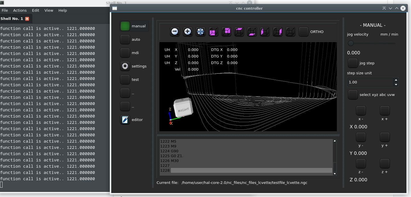
This is showing the cnc app, after loading the gcode drawing, it sends the gcode_data to hal side.
Then in the component itself it prints the ammount of gcode lines as a test : testing if component has gcode lines recieved.
Ok now this framework works and is quite compact.
At the left it prints the ammount of recieved gcode lines. This print is done by the hal component : state_machine.so
Yesterday i did some work at the gui interface.
Today i made a MILLTASK component for halcore that i named "state_machine.so"
This component will do the program logic like start, stop, pause etc. and also handles the jogging & trajectory stuff.
The state_machine.so component is using shared memory to load the gcode data from userspace.
All is done in c++ code.
So for uploading gcode to the hal side, no hal pins are required. It just's sends the data_structure containing the gcode
information to the kernel module. It's using a mutex.
This is showing the cnc app, after loading the gcode drawing, it sends the gcode_data to hal side.
Then in the component itself it prints the ammount of gcode lines as a test : testing if component has gcode lines recieved.
Ok now this framework works and is quite compact.
At the left it prints the ammount of recieved gcode lines. This print is done by the hal component : state_machine.so
Attachments:
The following user(s) said Thank You: tommylight, Clive S, Lcvette, Aciera, Darium, Unlogic
Please Log in or Create an account to join the conversation.
Time to create page: 2.958 seconds