Trajectory Planner using Ruckig Lib
- Grotius
-

- Offline
- Platinum Member
-

- Posts: 2419
- Thank you received: 2348
When i find some time later on, will run your values and report back.
@TheRoslyak,
If you grab the ~/vendor/scurve dir, there are trajectory examples that can run in a qt demo app. For jogging & auto mode.
You could try these out. It only uses qt dependencies, so you can run it i think without any nasty problems.
If you failed to do it, just let me know.
To advise about planner, i don't know what you wanna do. Run a gcode or run just a motor from a to b?
I have the sai interpreter stand alone running to load gcode data. The sai is little modified to get more info.
This goes ok. Maybe you can use it too.
@All,
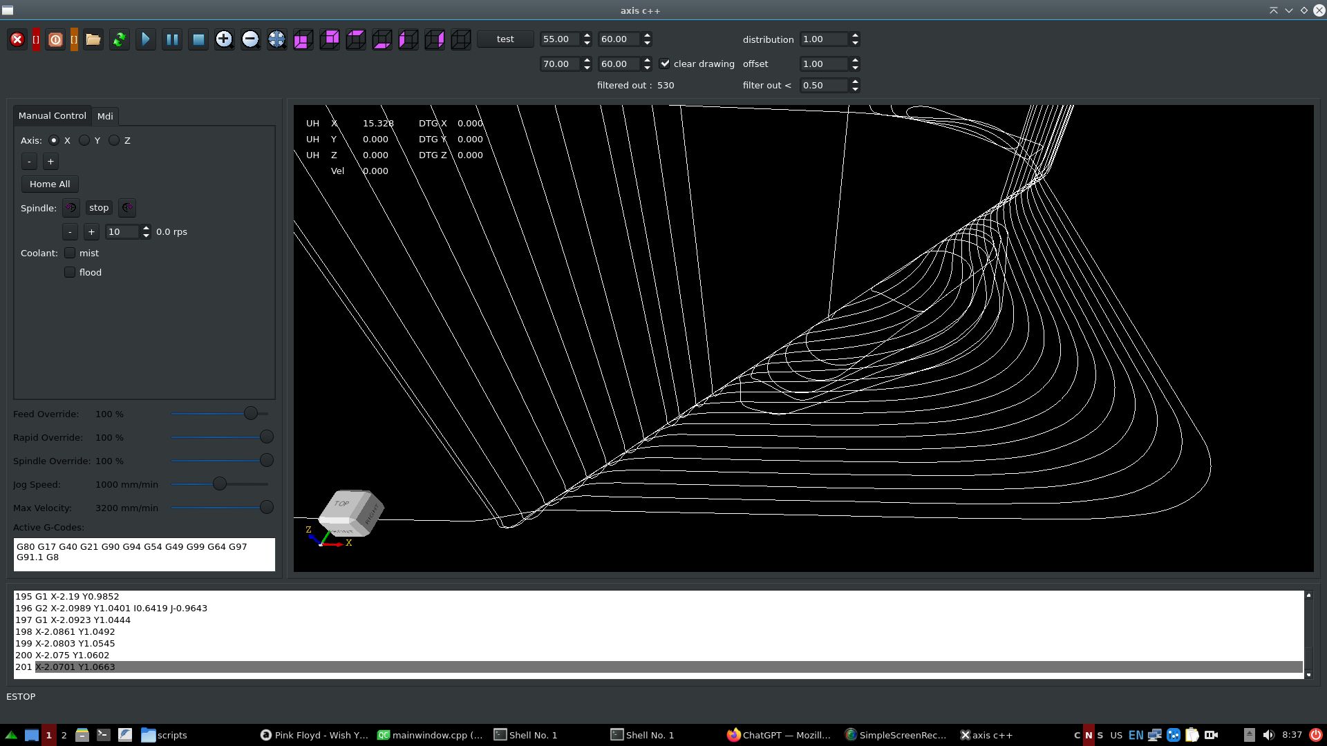
I started making a algo using a even distribution of waypoints. I thought yeahh good idea.
Then followed by an arc overlay.
Output was not ok for me. I have output picture on request.
In the end just adding fillets to corners, had the nicest output.
1. Coded the gcode to filter out tiny segments, given a filter value in mm. This is like a path compressor.
2. Then the path deviation is set by a offset value. This connects all gcode lines with tri-clothoids inbetween in 3d.
Gcode file from robh:
Filters out 530 lines. Transforms path into G2 continious.
Gcode file from lcevette:
Filters out 1455 lines. Transforms path into G2 continious.
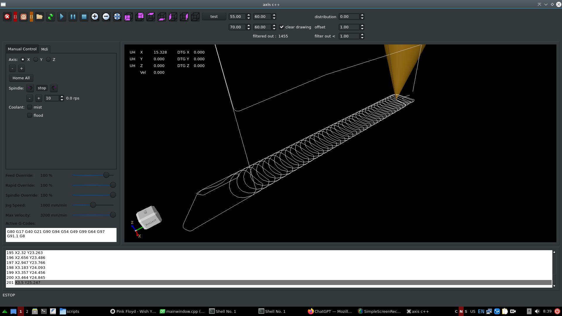
I think this output is a nice result for today. Now what should be done better?
Attachments:
Please Log in or Create an account to join the conversation.
- hmnijp
- Offline
- Senior Member
-

- Posts: 42
- Thank you received: 49
Great job!@All,
I started making...
I think this output is a nice result for today. Now what should be done better?
You can test 3D surface G-code with a large number of points. Its original surface is very smooth, without a sharp change in the direction of the tool path, which tells us that the speed graph should show a smooth speed without jumps, close to the maximum. Stops and speed changes create milling defects on the surface of the material due to shaking.
One important metric could be comparing code execution time with the old planner and other cnc - it is obvious that S-curves are slower on a trajectory with sharp corners, but on smooth surface in theory there should not be a very big difference. (as an example, a strong difference in execution time can be seen in the graphs in the message - these are the consequences of not compressing small segments into one overall curve with smooth acceleration - a separate S for each small segment increases the overall acceleration time.)
I can share a test G-code similar to the one used in real work, which I used to adjust the PQ parameters of the post processor. There are several types of operations(adaptive and surface finishing), and several variants of the same trajectory, but with a different number of points = using different parameters P. The execution time of the code at a fixed acceleration and speed is also written in the comments. (10k-200k lines, ±5min machinig time)
drive.google TP g-code tests
There is also a list of plans for the future:
2) We need to figure out how to solve the problem of mixing linear and rotary axes at the same time - this is a big problem with the current planner - it does not do smoothing when connecting any rotary axis, and this problem does not allow working with rotary axes at sufficient speed. A solution to this problem has been requested by all A/BC axle users for many years...
The question may arise: how to calculate the geometric accuracy of this path?
after all, smoothing with a certain tolerance may require inverse kinematic transformations. But I know that many take into account only XYZ axis tolerance, and separately speed-acceleration and angle tolerance limitations for each ABC axis. Maybe someone can give some ideas...
Another feature: when using rotary axes, inverse time feed G93 is usually used - which sets not the speed, but the execution time of each line of code = for synchronous movement of linear and angular axes. Without G93 it is impossible to control them simultaneously, because F1000 mm/min ≠ 1000degree/min.
Can calculating the average speed for each section complicate the compressor and planner algorithm?
g93-g94-g95
I also shared a couple of these files for tests.
3) The linuxcnc interpreter has support for interpolation G5 Cubic Spline, G5.1 Quadratic Spline, G5.2 G5.3 NURBS Block - They are not so popular, and there are few CAMs that can generate such code (mastercam and siemensNX can do this, with the corresponding post-processors), I'm not sure if they have an advantage over a good polyline smoothing algorithm, but at least it allows you to use less code to describe the curve. so it would be nice to use them for backward compatibility, maybe someone will need it...
g5-g5.1 splines, g5.2-g5.3 nurbs
One day I experimented with them, and recorded the log of speed and acceleration using them - it's similar to S-curve)
Please Log in or Create an account to join the conversation.
- Aciera
-

- Offline
- Administrator
-

- Posts: 4723
- Thank you received: 2116
I think that this would require blending tool position and tool orientation separately with deviation constraints defined for each.2) We need to figure out how to solve the problem of mixing linear and rotary axes at the same time - this is a big problem with the current planner - it does not do smoothing when connecting any rotary axis, and this problem does not allow working with rotary axes at sufficient speed. A solution to this problem has been requested by all A/BC axle users for many years...
Please Log in or Create an account to join the conversation.
- Grotius
-
- Offline
- Platinum Member
-
- Posts: 2419
- Thank you received: 2348
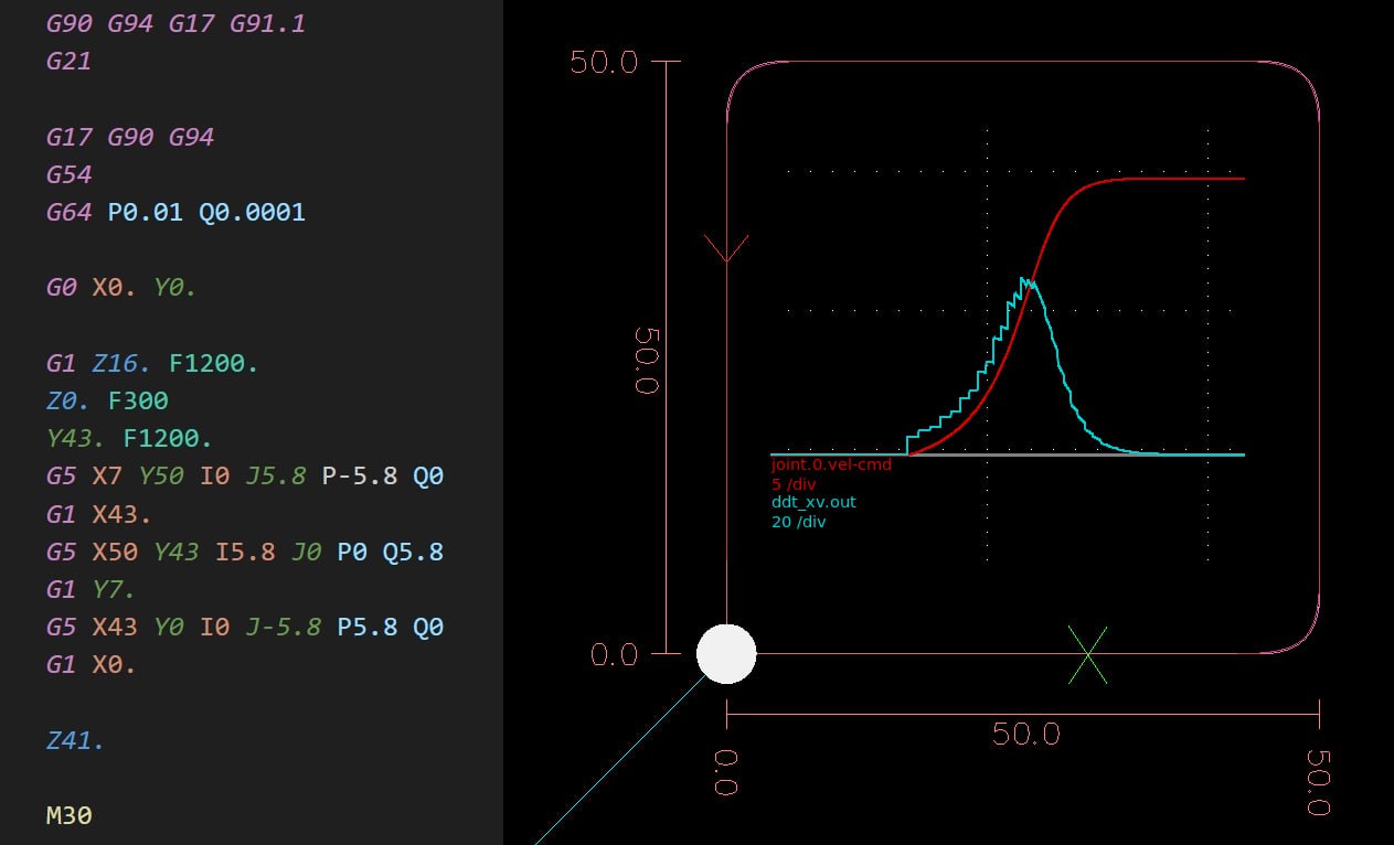
Here is the scurve doing 100 segments:
// Example auto mode.
double dist=1*25.4;
maxvel=100*25.4;
maxacc=50*25.4;
maxjer=20*25.4;
double a=0, b=0;
int nr=0;

for(uint i=0; i<100; i++){
    sc_segment seg;
    seg.pnt_s={a,0,0};
    seg.pnt_e={a+dist,0,0};
    seg.vo=0;
    seg.ve=0;
    seg.primitive_id=sc_primitive_id::sc_line;
    seg.type=sc_motion_type::sc_linear;
    seg.gcode_line_nr=nr;
    seg.path_lenght=dist; //lenght(seg.pnt_s,seg.pnt_e);
    vector_add_segment_c(ptr,seg);
    vector_at_id_set_tarpositions_c(ptr);

    a+=dist;
    nr++;
}Please Log in or Create an account to join the conversation.
- TheRoslyak
-

- Offline
- Elite Member
-

- Posts: 238
- Thank you received: 37
Essentially, I need to implement Pick and Place movements with conveyor tracking. I spent all day yesterday trying to install MoveIt2, but ultimately without success. ROS2 also needs to be installed, and I haven't managed to install any version of it either. I don't know where the problem lies. GPT suggested installing it in a Docker container, but that's not an option for me. If anyone has experience installing ROS2+MoveIt2 on Debian 12, I would love to hear about it.
I then tried to install Tesseract Planning, but it was not very successful either. One repository is broken or something like that. Ultimately, OMLP installed without any issues. It installed and compiled without major problems. The test program with Task thread Hal doesn't give any errors or latency warnings. However, the functionality and applicability are still unknown. Perhaps other libraries would be more suitable, but installing them has proven to be difficult.
Please Log in or Create an account to join the conversation.
- Aciera
-
- Offline
- Administrator
-
- Posts: 4723
- Thank you received: 2116
Please Log in or Create an account to join the conversation.
- Grotius
-
- Offline
- Platinum Member
-
- Posts: 2419
- Thank you received: 2348
Thanks for your mayor contribution again.
comparing code execution time with the old planner and other cnc
Yes this we can add on the todo list.
it is obvious that S-curves are slower on a trajectory with sharp corners.
This is just for info, in theory the scurve should use at least the same time as a trapezium curve.
I can share a test G-code similar to the one used in real work, which I used to adjust the PQ parameters of the post processor.
I found the P value, but the Q value, i still not found.
We need to figure out how to solve the problem of mixing linear and rotary axes at the same time.
This entiry abc uvw external axis section has to be coded in a proper way it will work out the different solutions.
Like in a science paper we must have a function flow paper. That walks it's way to the solution and is
reviewed by multiple people.
3) The linuxcnc interpreter has support for interpolation G5 Cubic Spline, G5.1 Quadratic Spline, G5.2 G5.3 NURBS Block -
Yes, in the past i have tried this.
If the planner has good smoothing algo's, maybe just let the planner do the work.
@Arciera,
When using 5 axis machine gcode.
The trajectory planner does the path blending offline now.
This is really nice! You can see the blended path before program start.
So when runnig the program online it's just following the blended path.
In theory it's not blending anymore, just following a blended path.
** A new development would be to update the blended gcode in the gcode viewer.
Adding the tri_clothoids or other exotics within the gcode.
This would simplify the trajectory planners execution, restart, pause etc.
Then the tool position xyz and tool orientation abc are just following the exact blended
path coordinates. Then synchronized motion xyz abc uvw is done by a function derived from
a function flow science paper.
Or do you think something else is better?
Attachments:
Please Log in or Create an account to join the conversation.
- Grotius
-
- Offline
- Platinum Member
-
- Posts: 2419
- Thank you received: 2348
If you don't need gcode, you can just use ruckig or any other scurve lib.
Ruckig works excellent if you dont need velocity ends, acceleration ends, don't need waypoints.
Then if you need to get a to position xyz, then interpolate the scurve over a 3d line.
Where lies your problem?
Please Log in or Create an account to join the conversation.
- TheRoslyak
-
- Offline
- Elite Member
-
- Posts: 238
- Thank you received: 37
Please Log in or Create an account to join the conversation.
- Grotius
-
- Offline
- Platinum Member
-
- Posts: 2419
- Thank you received: 2348
To get result fast, maybe use lcnc as it is.
Create a nml c++ mdi hook and just push mdi gcode commands into a queue.
In the past i created a program that used a text file buffer that had the coordinates.
It used hal streamer. The source is in the archive . Just look for info.
Here is how the lcnc c++ gui sends gcode commands :
QString mdi_text=ui->lineEdit_mdi_command->text();
 nml->mdi(mdi_text.toStdString());
 nml->mdi_execute();
This is the easyest way for you to get on going.
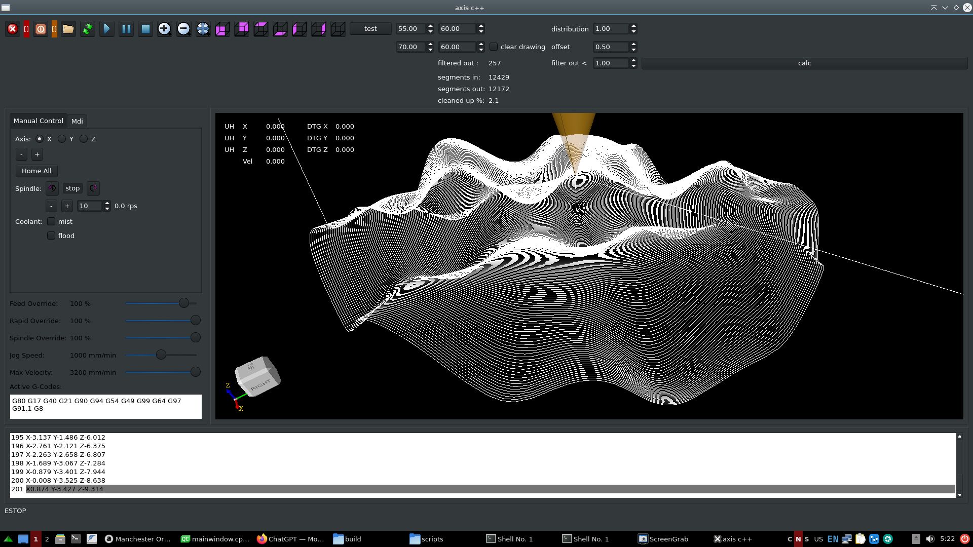
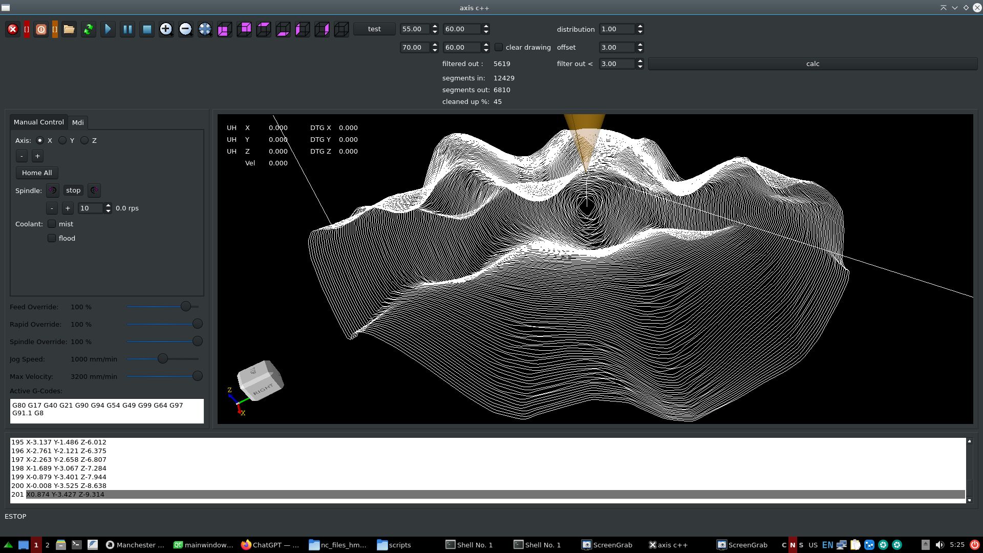
@All,
Did some test, given the gcode files by hmnijp.
Items<1mm are removed & tri_clothoid connected, saves 21%
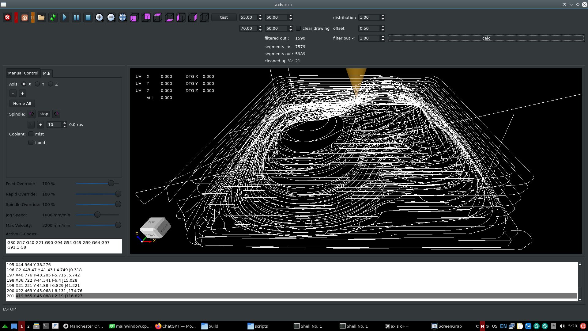
Items<5mm are removed & tri_clothoid connected, saves 58%

Items<1mm are removed & tri_clothoid connected, saves 2%
Items<3mm are removed & tri_clothoid connected, saves 45%
The files abobe ~20.000 - 30.000 lines will currently not load in opencascade. So i have to look
at a solution for that to minimize memory usage.
Attachments:
Please Log in or Create an account to join the conversation.