Trajectory Planner using Ruckig Lib
- Lcvette
-

- Offline
- Platinum Member
-

Less
More
- Posts: 1633
- Thank you received: 762
27 May 2024 16:41 #301603
by Lcvette
Replied by Lcvette on topic Trajectory Planner using Ruckig Lib
Excellent! That would be greatly appreciated @hmnijp
@grotius, I don't want this to hijack your thread in anyway, so let me know if this testing is helpful or if it is noise in your working thread and I will gladly move it elsewhere if so desired. ( I suspect it may be helpful, especially establishing baselines and real world testing on machines with speeds higher than stepper motor machine with ballscrews. my machine is not crazy fast but it is faster than most stepper dovetail conversions and has some mass too it ~6klbs with xy rapids of 708ipm and cuting feed rates maxxing out around 200ipm.
I am camming up a test part that doesn't waste too much stock material for each testing and would be happy to take input for features that would be good to test. I would gladly run the test using different trajectory planners, post processors, settings etc and film it. just let me know!
Chris
The following user(s) said Thank You: Grotius
Please Log in or Create an account to join the conversation.
- andrew2085
- Offline
- Junior Member
-

Less
More
- Posts: 27
- Thank you received: 40
28 May 2024 05:48 #301642
by andrew2085
Replied by andrew2085 on topic Trajectory Planner using Ruckig Lib
That library only implements line-to-line bi-clothoids from the paper. They only have a starting and ending angle because the curvature on the ends is zero to match a line's curvature. You also need the line-to-arc and arc-to-arc variations. Those are more complex to solve because there are more constraints. The clothoid needs to match the angle as well as the curvature of the arc at the point it joins.
You wouldn't fit the clothoid iteratively over the arc like that though, you use them to blend the joint's between lines to arcs, and arcs to arcs. The arc is already curvature continuous over itself, so there's no need to mess with it beyond whats needed for blending.
The s-curve solver I've been working on is almost done. Right now it averages 5700ns per solution on my PC. I'm not sure how that compares with other methods. I've mostly been spending time fixing corner cases where the precision is lower by having it solve billions of randomly generated problems until it detects something go wrong, then investigate and fix. The paper I was reading also didn't actually address the case where it isn't possible to reach the requested final velocity given the path length and initial velocity, so I had to figure that part out, but its working now.
I don't know how you're actually solving the s-curves now. But I imagine you must be projecting the 3d path and constraints down to one dimension and then solving right?
The following user(s) said Thank You: Grotius
Please Log in or Create an account to join the conversation.
- Grotius
-

- Offline
- Platinum Member
-
Less
More
- Posts: 2419
- Thank you received: 2348
28 May 2024 09:36 #301650
by Grotius
Replied by Grotius on topic Trajectory Planner using Ruckig Lib
@hmnijp,
Thank you for excellent contribution.
The zigzag example is a great example how to solve smooth path planning.
I think i know one exception for this example.
I like the picture where you have all the G64 [x][value] characters available for input.
If we just could choose a pluggable path solver in the linuxcnc gui, and it shows the result before program is running.
Offline optimalisation and preview, this would be perfect isnt it?
@Lcvette,
I don't want this to hijack your thread in anyway,
It's ok for me. No problem.
I would gladly run the test using different trajectory planners, post processors, settings etc and film it. just let me know!
That's nice to hear!
Yesterday i tested once again on the production machine. This time i was using the ngc file from robh.
It was a test, just to see how the planner worked on real machine using this tiny line segments.
When i enabled velocity end for next gcode line, when upcoming angle < 5 degrees. It was running a
velocity curve over the tiny lines without lowering speeds every tiny segment.
The machine gave no following error.
@Andrew,
That library only implements line-to-line bi-clothoids from the paper. They only have a starting and ending angle because the curvature on the ends is zero to match a line's curvature. You also need the line-to-arc and arc-to-arc variations. Those are more complex to solve because there are more constraints. The clothoid needs to match the angle as well as the curvature of the arc at the point it joins.
Indeed i have not seen clothoid's doing a line-arc G2 solving. a 3D clothoid would be nice. In science papers they
are talking about this 3d clothoid. But i have not looked further into it.
The paper I was reading also didn't actually address the case where it isn't possible to reach the requested final velocity given the path length and initial velocity, so I had to figure that part out, but its working now.
This is common indeed. In my algo it outputs a lower ve, if ve can not be reached. The path lenght is crucial.
I don't know how you're actually solving the s-curves now.
The scurve planner is only solving one input motion at a time. So a gcode line or arc is one motion.
It takes the path_begin, path_end, vo, ve, vm, jerk, as inputs and calculates the scurve.
If you are halfway the motion and give a new path_end position, this is no problem for the algo.
The cycletime is also a input parameter for the algo. But this can give problems, because it's a divider.
So when you have a strange cycletime 0.022 and a pathlenght of 100mm. It happens that you can simply not reach
endpoint. The algo endpoint can be 99.999987 or 100.000225 for example. To solve that problem in the
downcurve i use a extra divider that solves the difference i mention above over the downcurve cycles. It's like cheating,
but it works perfect.
But I imagine you must be projecting the 3d path and constraints down to one dimension and then solving right?
Yes, 1 dimension. Just an array of line lenghts to solve. And you got info about vo,ve,vm,acs,ace for each line.
I count them up.
line_0 lenght = 100mm
line_0 start = 0
line_0 end = 100
line_1 lenght = 150
line_0 start = 100
line_0 end = 250
and so on.
Please Log in or Create an account to join the conversation.
- Grotius
-
- Offline
- Platinum Member
-
Less
More
- Posts: 2419
- Thank you received: 2348
28 May 2024 10:55 #301657
by Grotius
Replied by Grotius on topic Trajectory Planner using Ruckig Lib
@mr Morley,
The g64 P tollerance is set by this function in the planner code :
int tpSetTermCond(TP_STRUCT * const tp, int cond, double tolerance){
tp->termCond = cond;
tp->tolerance = tolerance;
printf("tpSetTermCond, tollerance: %f \n",tp->tolerance);
return 0;
}
Then where should be the Q value to be found in the source? For G64 P0.1 Q1
Q is of type integer, turns on or off native cam.
@All,
I was thinking about the planner and the last contributions on this thread.
Today i want to do a test to load gcode and try to perform a heavy calculation that exceeds the planner's cycletime,
If we can make this work, we can perform the whole path optimalisation at once. I think we create a thread for this that
run's seperate from the planners cycle. Otherwise a signal 11 will occur, followed by a memory dump.
Then i think we have to use a opencascade cad viewer to simply demonstrate path optimalisation in the lcnc gui.
This then can be done offline, before program starts.
In this way, user just can select a optimalisation strategy. For me it's now difficult to see blending result at forehand
without opencascade.
Please Log in or Create an account to join the conversation.
- Grotius
-
- Offline
- Platinum Member
-
Less
More
- Posts: 2419
- Thank you received: 2348
28 May 2024 12:29 #301670
by Grotius
Replied by Grotius on topic Trajectory Planner using Ruckig Lib
To enable extensive computations in the planner added
seperate thread creation
And when all gcode is loaded we request exstensive calculation by calling start calculation thread
This then is the framework to create a path optimalisation without staying within the planner cycletime.
Now next thing to test is running the c++ linuxcnc axis gui wich has the gremlin opencascade viewer under the hood.
Here we can show the original gcode path, and the updated gcode path, this then can be done offline, or online.
The following user(s) said Thank You: John313
Please Log in or Create an account to join the conversation.
- andrew2085
- Offline
- Junior Member
-
Less
More
- Posts: 27
- Thank you received: 40
28 May 2024 16:16 #301685
by andrew2085
Replied by andrew2085 on topic Trajectory Planner using Ruckig Lib
This seems like the right way to do it. I don't know much about the LinuxCNC internals, but I think the blending and s-curve planning should all be happening non-real-time. Once the plan has been updated it can be passed to the real-time thread where its job is to just follow the plan. The number of segments in the plan should be large enough so that during normal operation the real-time thread doesn't run out of segments to follow before the plan is updated by the non-real-time thread. I think the last segment of the plan should always end in zero velocity in case the real-time thread does actually reach it. I think that would have to happen anyway if for example in the g-code you have an if statement or a loop. You can't plan beyond that because the conditions should be evaluated once the machine has actually reached that point.
I put the s-curve stuff I've been working on here: github.com/a-downing/scurvy. I didn't realize you were working off the same paper as I was. For some reason I though you were solving it iteratively.
I might look at that bi-clothoid blending paper.
I put the s-curve stuff I've been working on here: github.com/a-downing/scurvy. I didn't realize you were working off the same paper as I was. For some reason I though you were solving it iteratively.
I might look at that bi-clothoid blending paper.
The following user(s) said Thank You: Grotius
Please Log in or Create an account to join the conversation.
- hmnijp
- Offline
- Senior Member
-

Less
More
- Posts: 42
- Thank you received: 49
28 May 2024 16:18 #301686
by hmnijp
There have been proposals to move path calculations to non-realtime, and it seems to be working successfully there.
forum.linuxcnc.org/38-general-linuxcnc-q...on-real-time?start=0
OpenCN also does trajectory optimization (feedopt) in non-realtime.
Also, inverse kinematic transformations for 5axis with RTCP require a lot of calculations. There were many opinions that this also requires moving path planning to non-realtime and doing sequential execution from a buffer. This may have to be done in the future...
There is one more thing that you may need to consider - 3D processing programs are often very large. sometimes it’s 100-200MB of code. In the current implementation, the interpreter loads the entire list, taking up a lot of RAM.
G64 is not standardized. Each CNC has its own parameters for setting up its planner version (Siemens cycle 832, fanuc g05.1, etc.), moreover, they changed and added new parameters in each new version. A common method is when many settings are made in the GUI(ini), and while g-code is running, presets for roughing or finishing operations (roughing lvl) are switched.
If your code requires changes and new variables to configure the path, I don’t think this will be a big problem, because the algorithms may become different.
The only relatively common parameter is tolerance.
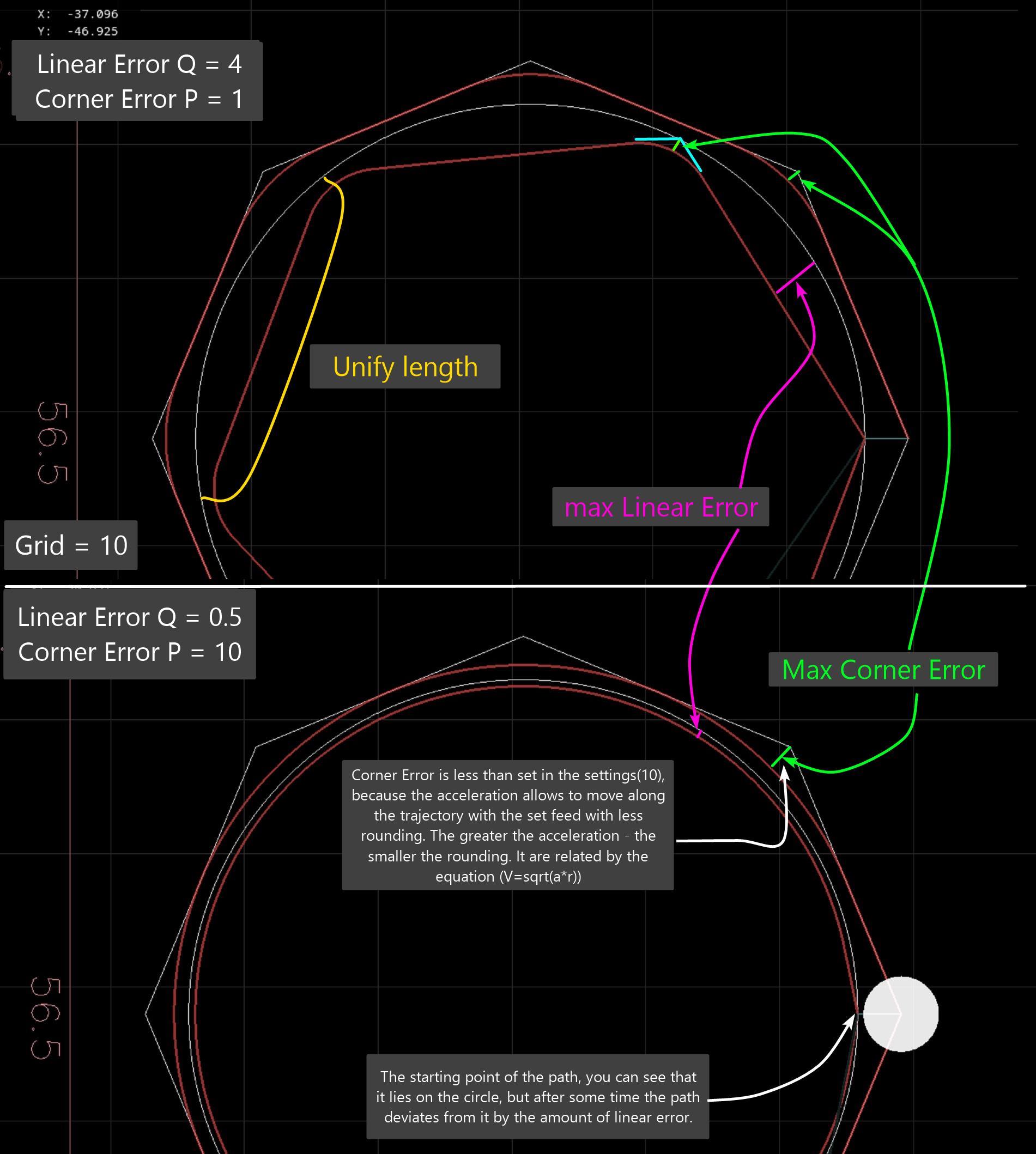
The current planner has two different tolerances - Q for deviation of the naive cam from straight sections, and P for deviation from corners.. This is not entirely obvious to users. Two parameters are needed only for the old planner algorithm...
a picture showing how using different combinations of P and Q naive cam can make a circle from a polygon, and a polygon from a circle in the code. Naive cam first divides the circle into straight lines with deviation Q, then they are rounded with deviation P from the corners.
Replied by hmnijp on topic Trajectory Planner using Ruckig Lib
Check out the discussions in this thread.
The g64 P tollerance is set by this function in the planner code :
int tpSetTermCond(TP_STRUCT * const tp, int cond, double tolerance){
tp->termCond = cond;
tp->tolerance = tolerance;
printf("tpSetTermCond, tollerance: %f \n",tp->tolerance);
return 0;
}
Then where should be the Q value to be found in the source? For G64 P0.1 Q1
Q is of type integer, turns on or off native cam.
@All,
I was thinking about the planner and the last contributions on this thread.
Today i want to do a test to load gcode and try to perform a heavy calculation that exceeds the planner's cycletime,
If we can make this work, we can perform the whole path optimalisation at once. I think we create a thread for this that
run's seperate from the planners cycle. Otherwise a signal 11 will occur, followed by a memory dump.
Then i think we have to use a opencascade cad viewer to simply demonstrate path optimalisation in the lcnc gui.
This then can be done offline, before program starts.
In this way, user just can select a optimalisation strategy. For me it's now difficult to see blending result at forehand
without opencascade.
There have been proposals to move path calculations to non-realtime, and it seems to be working successfully there.
forum.linuxcnc.org/38-general-linuxcnc-q...on-real-time?start=0
OpenCN also does trajectory optimization (feedopt) in non-realtime.
Also, inverse kinematic transformations for 5axis with RTCP require a lot of calculations. There were many opinions that this also requires moving path planning to non-realtime and doing sequential execution from a buffer. This may have to be done in the future...
There is one more thing that you may need to consider - 3D processing programs are often very large. sometimes it’s 100-200MB of code. In the current implementation, the interpreter loads the entire list, taking up a lot of RAM.
G64 is not standardized. Each CNC has its own parameters for setting up its planner version (Siemens cycle 832, fanuc g05.1, etc.), moreover, they changed and added new parameters in each new version. A common method is when many settings are made in the GUI(ini), and while g-code is running, presets for roughing or finishing operations (roughing lvl) are switched.
If your code requires changes and new variables to configure the path, I don’t think this will be a big problem, because the algorithms may become different.
The only relatively common parameter is tolerance.
The current planner has two different tolerances - Q for deviation of the naive cam from straight sections, and P for deviation from corners.. This is not entirely obvious to users. Two parameters are needed only for the old planner algorithm...
a picture showing how using different combinations of P and Q naive cam can make a circle from a polygon, and a polygon from a circle in the code. Naive cam first divides the circle into straight lines with deviation Q, then they are rounded with deviation P from the corners.
Attachments:
The following user(s) said Thank You: tommylight, Grotius
Please Log in or Create an account to join the conversation.
- Grotius
-
- Offline
- Platinum Member
-
Less
More
- Posts: 2419
- Thank you received: 2348
28 May 2024 17:38 #301691
by Grotius
Replied by Grotius on topic Trajectory Planner using Ruckig Lib
@hmnijp,
, the interpreter loads the entire list, taking up a lot of RAM.
For the gcode preview it loads the entire list.
In the planner the interpreter sends a bulk of lines that are in between G0 moves. This consumes little memory.
Sometimes i see about 100 lines in the buffer, but there are also times there are 10 lines buffered.
I will make a hal_u32_t pin for it to count the extrema of the used buffer size and report later.
G64 is not standardized.
I don't know if actually multiple G64 commands are valid in the gcode. Never did that.
In the lcnc interpreter, so far i know there is only the P word to pass a value. The example you provided using
multipe chars would be nice to have in lcnc. I have modified the sai (stand alone interpreter) to retrieve more information
about the loaded gcode. But this in the sence of current plane, positions etc.
I never used anything from naive cam. So i have no experience using that.
@Andrew,
This seems like the right way to do it. I don't know much about the LinuxCNC internals, but I think the blending and s-curve planning should all be happening non-real-time.
There are a few things to mention. If you change the vm at runtime, you can't go non-realtime planning the scurve.
Blending current and upcoming segments, can done in realtime, blending more, use non-realtime.
Once the plan has been updated it can be passed to the real-time thread where its job is to just follow the plan.
This is correct.
The number of segments in the plan should be large enough so that during normal operation the real-time thread doesn't run out of segments to follow before the plan is updated by the non-real-time thread.
There is a period when the interpreter dumps new lines. This period is during a G0. During this period the non realtime
thread can do the path planning. For huge g1 content, this may take time. But machine may start moving the first segment. As
usually the first new G0 may stay as it is.
Another method is to request a interpreter gcode dump, right after the first dump is optimized and running.
I think the last segment of the plan should always end in zero velocity in case the real-time thread does actually reach it. I think that would have to happen anyway if for example in the g-code you have an if statement or a loop. You can't plan beyond that because the conditions should be evaluated once the machine has actually reached that point.
Yes.
For some reason I though you were solving it iteratively.
I have made more scurve libs in the past. The first one's where using sampling.
I might look at that bi-clothoid blending paper.
Ok, nice.
Please Log in or Create an account to join the conversation.
- Grotius
-
- Offline
- Platinum Member
-
Less
More
- Posts: 2419
- Thank you received: 2348
28 May 2024 17:56 #301695
by Grotius
Replied by Grotius on topic Trajectory Planner using Ruckig Lib
@Mr. Morley,
I have a question about starting a linux cnc gui.
This is my output :
user@debian10:~/linuxcnc/scripts$ linuxcnc
LINUXCNC - 2.10.0~pre0
Machine configuration directory is '/home/user/linuxcnc/configs/sim/axis'
Machine configuration file is 'qt_axis_mm.ini'
Starting LinuxCNC...
linuxcncsvr (488746) emcsvr: machine 'LinuxCNC-HAL-SIM-AXIS' version '1.1'
linuxcnc TPMOD=tpmod HOMEMOD=homemod EMCMOT=motmod
Note: Using POSIX realtime
milltask (488761) task: machine 'LinuxCNC-HAL-SIM-AXIS' version '1.1'
halui (488764) halui: machine 'LinuxCNC-HAL-SIM-AXIS' version '1.1'
Found file(lib): /home/user/linuxcnc/lib/hallib/core_sim.hal
Found file(lib): /home/user/linuxcnc/lib/hallib/sim_spindle_encoder.hal
Found file(lib): /home/user/linuxcnc/lib/hallib/axis_manualtoolchange.hal
Found file(lib): /home/user/linuxcnc/lib/hallib/simulated_home.hal
Found file(REL): ./cooling.hal
USRMOT: ERROR: command 30 timeout
This starts a qt c++ app from the ini file. However this gui only starts correclty, i mean you can jog, home etc.
if an axis gui is already running.
Did i miss something related to USRMOT?
Please Log in or Create an account to join the conversation.
- hmnijp
- Offline
- Senior Member
-
Less
More
- Posts: 42
- Thank you received: 49
28 May 2024 18:28 #301699
by hmnijp
The beginning of the program is roughing. At the end is finishing, and the G64 parameters change accordingly.
Replied by hmnijp on topic Trajectory Planner using Ruckig Lib
Yes, this is required.@hmnijp,
I don't know if actually multiple G64 commands are valid in the gcode. Never did that.
The beginning of the program is roughing. At the end is finishing, and the G64 parameters change accordingly.
The following user(s) said Thank You: Grotius
Please Log in or Create an account to join the conversation.
Time to create page: 0.546 seconds