Search Results (Searched for: )
- PedPEx
- PedPEx
14 Jun 2026 11:14
")
- jarcysgru
- jarcysgru
14 Jun 2026 10:41
- Alex
- Alex
14 Jun 2026 10:25 - 14 Jun 2026 10:26
Replied by Alex on topic please help five Axis with Vismach simulation and Mesa 7i96S
please help five Axis with Vismach simulation and Mesa 7i96S
Category: General LinuxCNC Questions
- bedouno
- bedouno
14 Jun 2026 02:30
Replied by bedouno on topic HAL component for tangential knife
HAL component for tangential knife
Category: HAL
- jayem1427
- jayem1427
14 Jun 2026 01:13
- Masiwood123

13 Jun 2026 23:51
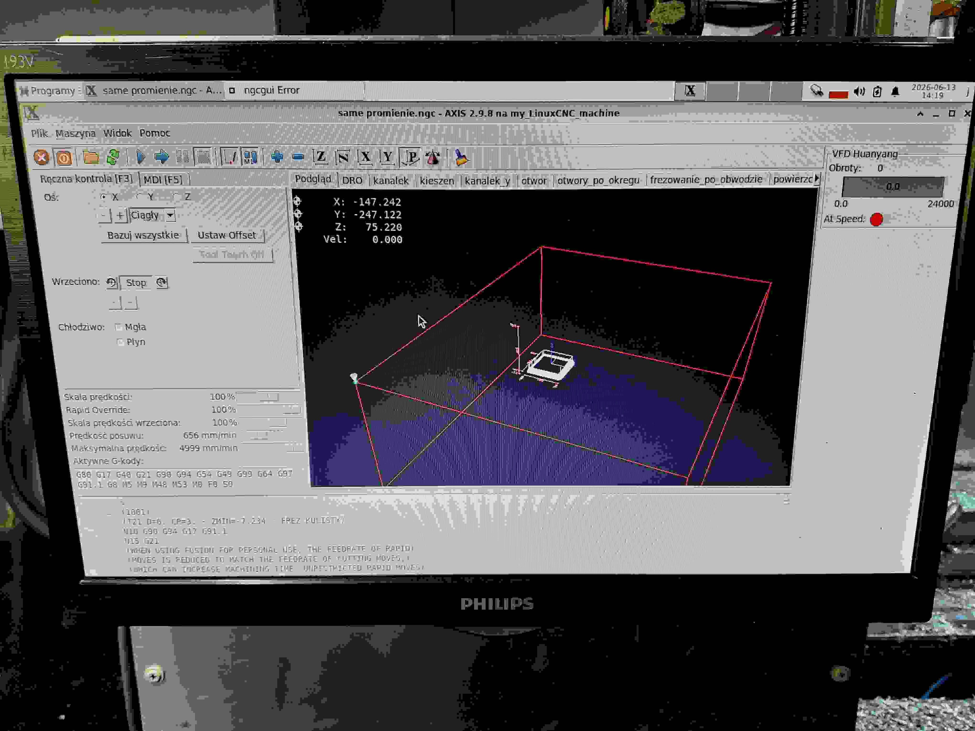
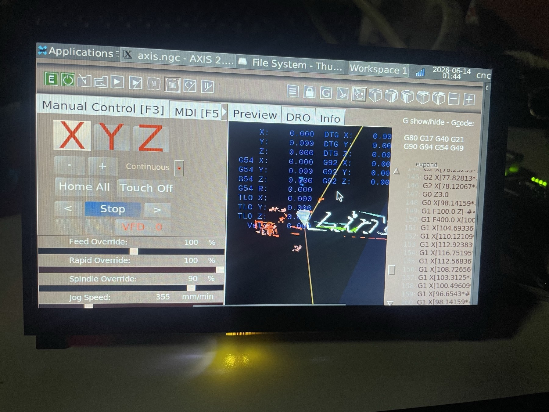
Replied by Masiwood123 on topic Axis 2 - touchscreen version of old friend
Axis 2 - touchscreen version of old friend
Category: AXIS
- tommylight

13 Jun 2026 22:40
Replied by tommylight on topic neuer linux cnc nutzer hat probleme mit steuerkarte
neuer linux cnc nutzer hat probleme mit steuerkarte
Category: Deutsch
- hermano
- hermano
13 Jun 2026 18:37
Replied by hermano on topic neuer linux cnc nutzer hat probleme mit steuerkarte
neuer linux cnc nutzer hat probleme mit steuerkarte
Category: Deutsch
- jeffmaxwell
- jeffmaxwell
13 Jun 2026 18:22
Replied by jeffmaxwell on topic Steps to make a bootable USB to install LinuxCNC.
Steps to make a bootable USB to install LinuxCNC.
Category: General LinuxCNC Questions
- Aciera

13 Jun 2026 18:09
Replied by Aciera on topic linuxcnc ohne endschlter
linuxcnc ohne endschlter
Category: General LinuxCNC Questions
- NWE

13 Jun 2026 17:20 - 13 Jun 2026 17:43

- karlhe
- karlhe
13 Jun 2026 16:31
Replied by karlhe on topic Maschine faehrt Endschlter nicht an
Maschine faehrt Endschlter nicht an
Category: General LinuxCNC Questions
- karlhe
- karlhe
13 Jun 2026 14:54
linuxcnc ohne endschlter was created by karlhe
linuxcnc ohne endschlter
Category: General LinuxCNC Questions
- grossm5000
- grossm5000
13 Jun 2026 13:05
Replied by grossm5000 on topic Differential encoder hard crashes the PC MESA7i77
Differential encoder hard crashes the PC MESA7i77
Category: Driver Boards
- timo
- timo
13 Jun 2026 12:03 - 13 Jun 2026 12:36
Replied by timo on topic neuer linux cnc nutzer hat probleme mit steuerkarte
neuer linux cnc nutzer hat probleme mit steuerkarte
Category: Deutsch
Time to create page: 0.361 seconds