Search Results (Searched for: )
- ississ

30 Jun 2026 18:58
")
- Aciera

30 Jun 2026 18:53 - 30 Jun 2026 19:05
- ALS
- ALS
30 Jun 2026 18:34
- Etced
- Etced
30 Jun 2026 18:15
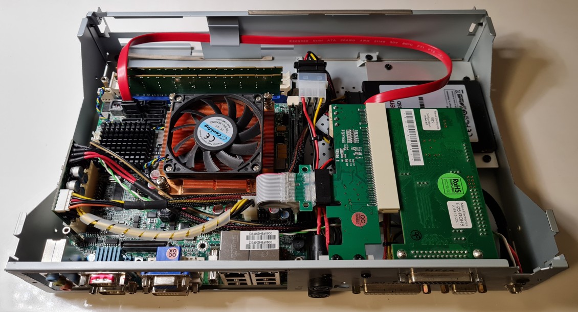
Can not connect to Mesa 7176eu was created by Etced
Can not connect to Mesa 7176eu
Category: Driver Boards
- muddiver
- muddiver
30 Jun 2026 17:24
Replied by muddiver on topic Tipps für aktuelle LinuxCNC Hardware gesucht
Tipps für aktuelle LinuxCNC Hardware gesucht
Category: Deutsch
- muddiver
- muddiver
30 Jun 2026 14:29
Replied by muddiver on topic Tipps für aktuelle LinuxCNC Hardware gesucht
Tipps für aktuelle LinuxCNC Hardware gesucht
Category: Deutsch
- Ul
- Ul
30 Jun 2026 13:48 - 30 Jun 2026 13:56
Replied by Ul on topic Tipps für aktuelle LinuxCNC Hardware gesucht
Tipps für aktuelle LinuxCNC Hardware gesucht
Category: Deutsch
- muddiver
- muddiver
30 Jun 2026 13:18 - 30 Jun 2026 13:36
Replied by muddiver on topic Tipps für aktuelle LinuxCNC Hardware gesucht
Tipps für aktuelle LinuxCNC Hardware gesucht
Category: Deutsch
- Estley
- Estley
30 Jun 2026 12:50
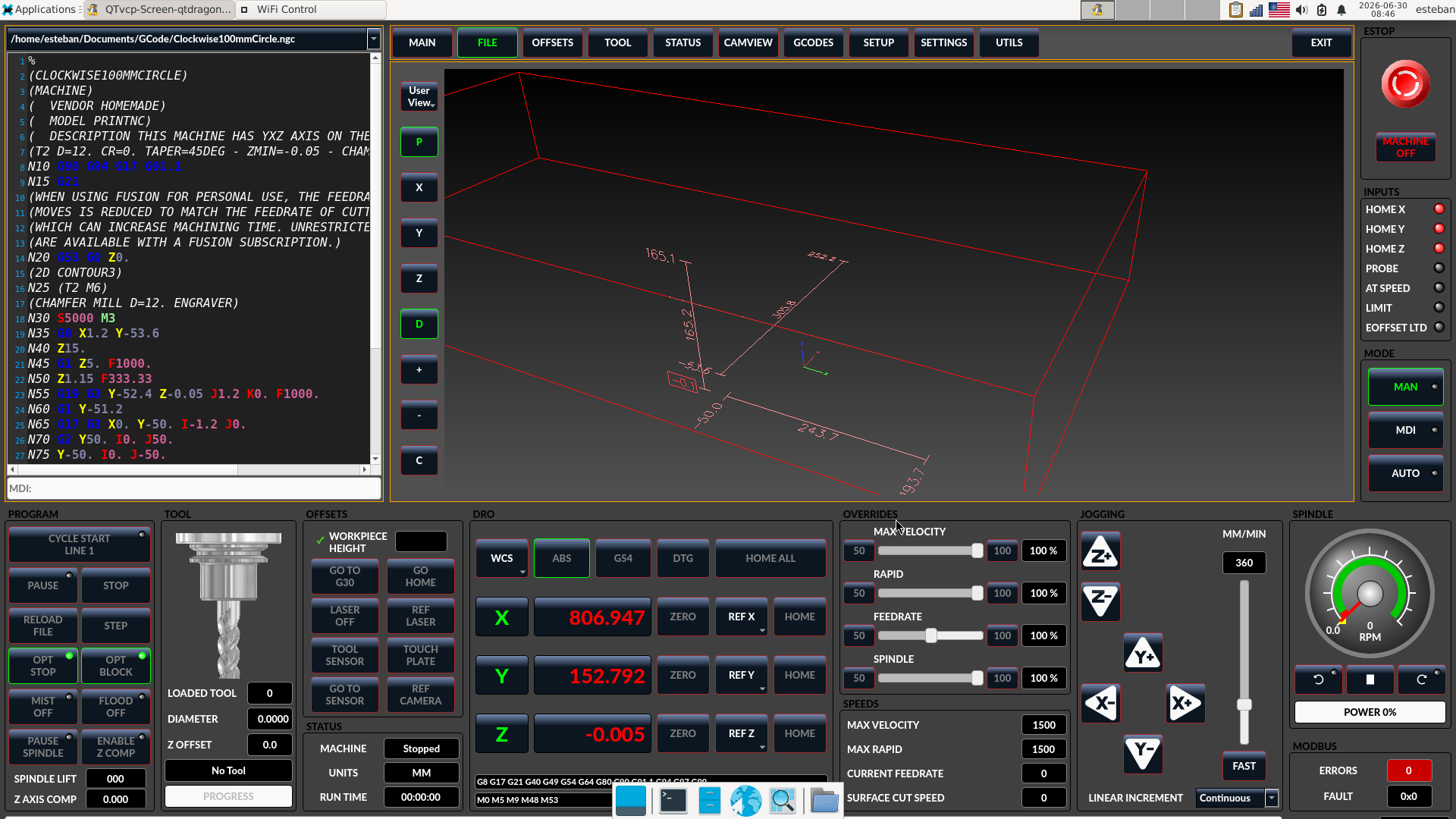
Toolpaths not displaying in QT Dragon was created by Estley
Toolpaths not displaying in QT Dragon
Category: Qtvcp
- ruslanemtsov
- ruslanemtsov
30 Jun 2026 09:23
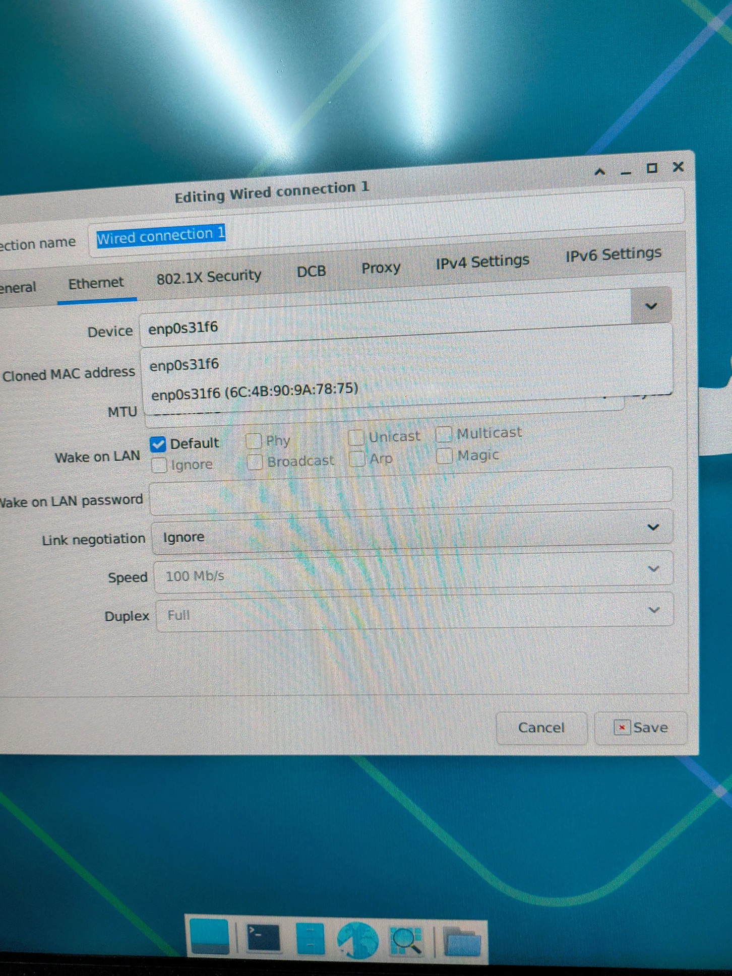
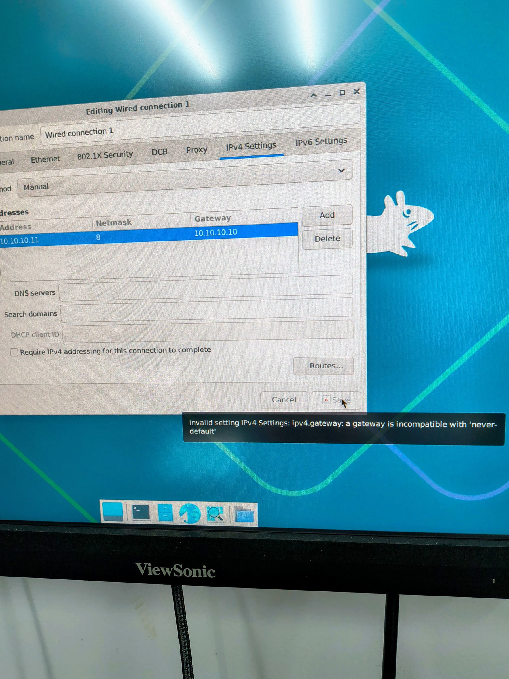
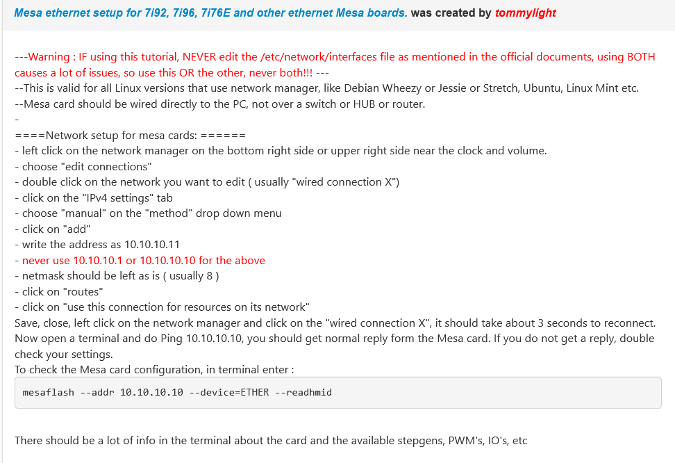
Replied by ruslanemtsov on topic Ethercat drive configuration woes
Ethercat drive configuration woes
Category: EtherCAT
- umerov
- umerov
30 Jun 2026 05:40
- cmorley
- cmorley
30 Jun 2026 02:17
- tommylight

30 Jun 2026 01:00
Replied by tommylight on topic Retrofitting a 3-axis VMC with DC servos - guidance needed
Retrofitting a 3-axis VMC with DC servos - guidance needed
Category: Driver Boards
")
- PCW

29 Jun 2026 23:56
- Japoo_Ness
- Japoo_Ness
29 Jun 2026 23:07
Replied by Japoo_Ness on topic Retrofitting a 3-axis VMC with DC servos - guidance needed
Retrofitting a 3-axis VMC with DC servos - guidance needed
Category: Driver Boards
Time to create page: 0.387 seconds