Search Results (Searched for: 7i77 spindle)
- Benb

13 Aug 2024 01:50
- warreng
- warreng
10 Aug 2024 15:30
- RotarySMP

30 Jul 2024 08:29
Replied by RotarySMP on topic Verify my Mesa selection
Verify my Mesa selection
Category: Driver Boards
- Krulli_Fräser
- Krulli_Fräser
30 Jul 2024 05:28
Verify my Mesa selection was created by Krulli_Fräser
Verify my Mesa selection
Category: Driver Boards
- Becksvill
- Becksvill
26 Jul 2024 10:45
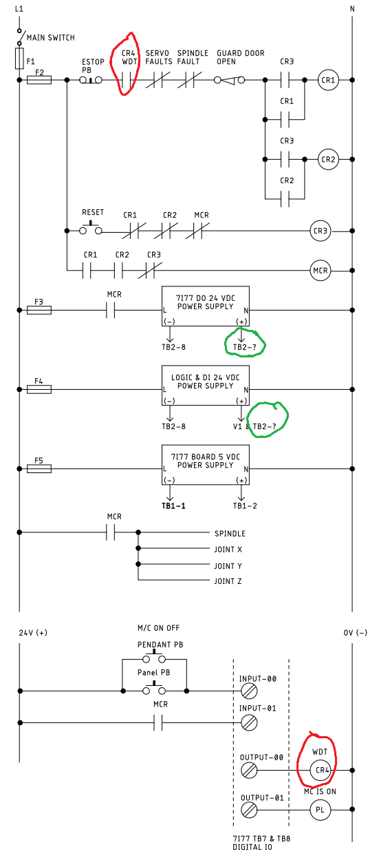
Replied by Becksvill on topic big 5axis mazak horizontal cnc mill
big 5axis mazak horizontal cnc mill
Category: Show Your Stuff
Time to create page: 0.751 seconds