THCAD-10 + hypertherm 45 (nonXP)
- andypugh
-

- Offline
- Moderator
-

Less
More
- Posts: 19875
- Thank you received: 4642
06 Oct 2017 14:12 #100007
by andypugh
Replied by andypugh on topic THCAD-10 + hypertherm 45 (nonXP)
www.mouser.com/pdfdocs/alphawire-Underst...g-Shielded-Cable.pdf says
"Usually, rather than attempting to ground the entire shield, the drain wire is used to terminate
and ground the shield."
(That uninsulated wire is the drain wire)
"Usually, rather than attempting to ground the entire shield, the drain wire is used to terminate
and ground the shield."
(That uninsulated wire is the drain wire)
The following user(s) said Thank You: cruzinone
Please Log in or Create an account to join the conversation.
- cruzinone
- Offline
- Junior Member
-

Less
More
- Posts: 27
- Thank you received: 0
06 Oct 2017 14:24 #100010
by cruzinone
Replied by cruzinone on topic THCAD-10 + hypertherm 45 (nonXP)
That drain wire is hooked to pin 13 on the cable I got from hypertherm. What do you suggest I do with it. Hook it up to the thcad-10 where the manual for the thcad calls for shield? I will read the link you sent me and see if I can gather understanding. thanks andypugh
Please Log in or Create an account to join the conversation.
- robertspark
- Offline
- Platinum Member
-

Less
More
- Posts: 915
- Thank you received: 216
06 Oct 2017 17:27 #100019
by robertspark
Replied by robertspark on topic THCAD-10 + hypertherm 45 (nonXP)
Yes, connect it to the shield pin of the thcad-10
Please Log in or Create an account to join the conversation.
- andypugh
-
- Offline
- Moderator
-
Less
More
- Posts: 19875
- Thank you received: 4642
06 Oct 2017 18:17 #100023
by andypugh
Replied by andypugh on topic THCAD-10 + hypertherm 45 (nonXP)
Generally the advice is to ground the shield at only one end.
Please Log in or Create an account to join the conversation.
- rodw
-

- Offline
- Platinum Member
-
Less
More
- Posts: 11990
- Thank you received: 4084
06 Oct 2017 18:30 #100025
by rodw
Replied by rodw on topic THCAD-10 + hypertherm 45 (nonXP)
Just hook it up and see what happens. Its not an electrical signal so you are not going to blow something up. Use halscope to see how clean the divided voltage signal is in a live cut
If you get a noisy signal something like this rather than the clean plots published earlier on this thread, then you have a noise issue.
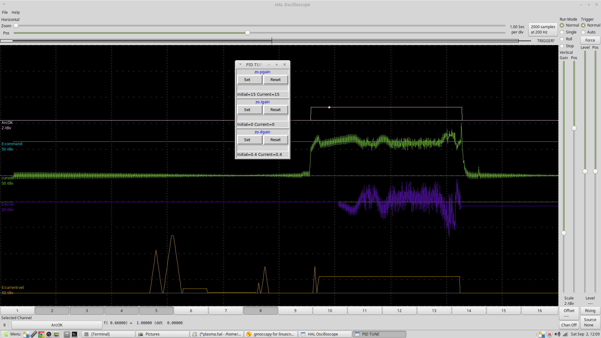
If noisy try disconnecting the drain wire from the THCAD and see if it improves so the cable screen is only connected at the plasma end.
You can see that the noise shows up on 0 volts so just connecting things up and powering up your plasma cutter without cutting is probably all you need to do initially to find out if it is likely to be a problem.
If you get a noisy signal something like this rather than the clean plots published earlier on this thread, then you have a noise issue.
If noisy try disconnecting the drain wire from the THCAD and see if it improves so the cable screen is only connected at the plasma end.
You can see that the noise shows up on 0 volts so just connecting things up and powering up your plasma cutter without cutting is probably all you need to do initially to find out if it is likely to be a problem.
Please Log in or Create an account to join the conversation.
- cruzinone
- Offline
- Junior Member
-
Less
More
- Posts: 27
- Thank you received: 0
07 Oct 2017 12:20 #100038
by cruzinone
Replied by cruzinone on topic THCAD-10 + hypertherm 45 (nonXP)
thanks to all.
Please Log in or Create an account to join the conversation.
- kb8wmc
-
- Offline
- Premium Member
-

Less
More
- Posts: 95
- Thank you received: 4
11 Feb 2018 15:01 #105745
by kb8wmc
Replied by kb8wmc on topic THCAD-10 + hypertherm 45 (nonXP)
On my brother's plasma table after completing the first cut, the torch does not raise high enough to do touch off for the second cut and I get an error that the Z axis would exceed negative limits on attempt to touch off for next cut...
We are using JT's touch off subroutine, the only change being the distance for the touch off (1.25")...Also using JT's post-processor in sheet cam...
The one thing to note is that when making the gcode in sheet cam and when then viewed in linuxcnc, there are two different elevations the objects to be cut are placed on...I have posted questions in the sheet cam forum related to this but as yet no responses...
Any suggestions will be appreciated...
Thanks in advance
Please Log in or Create an account to join the conversation.
- rodw
-
- Offline
- Platinum Member
-
Less
More
- Posts: 11990
- Thank you received: 4084
11 Feb 2018 20:22 #105763
by rodw
Replied by rodw on topic THCAD-10 + hypertherm 45 (nonXP)
It is possible that you are losing steps on the Z axis (eg your velocity and acceleration is too high).
More likely it is software.
I would start at the beginning and write some gcode by hand that does something simple that works. Once you are certain it is all working as expected, then look at the sheetcam generated g code to see what its doing wrong. Then edit the sheetcam post processor to modify the sheetcam post processor file so it does what you want.
Please Log in or Create an account to join the conversation.
- kb8wmc
-
- Offline
- Premium Member
-
Less
More
- Posts: 95
- Thank you received: 4
08 May 2018 15:00 #110384
by kb8wmc
Replied by kb8wmc on topic THCAD-10 + hypertherm 45 (nonXP)
Rod,
Sorry it has taken so long to get back...
There is no loss of steps in Z...You are correct that the issue seems to lie in software...
We have more information now that we have had time to use the machine and evaluate what is going on...To further clarify the actual machine setup I provide the following:
We are using SheetCAM TNG for G-code generation...The post processor we use in SheetCAM is the post developed by John Thornton...We have made no changes to his post with one minor exception of raising the Z torch upon completion of the final cut (next to the last line of code) instead of sending the torch to Z0...For all intents and purposes this works perfectly...
Next is the subroutine (also developed by JT) which is called for touch-offs, pierce height, starting torch, etc...This sub has only been modified in the switch hysteresis (had to increase to 0.23" based upon machine design) and when using this sub when importing the created G-code into LinuxCNC the objects to be cut by the torch when viewed from any view except the Z top view appear on different layers...When doing the actual cut it all works okay, but I get an error message box stating that the code exceeds minimum Z limits when there are more than 3 cuts to be done, do you want to proceed anyway...Clicking yes starts the cutting process and completes properly...
From within the subroutine code I commented out the G92 setting the Z to zero, by doing that when viewing the objects to be cut in all the various views all objects appear on the same elevation...I have tested this without doing actual cutting and it seems to go through all processes properly, but I am a little nervous about running it this way...
As a work-around I have envisioned setting the Z limits in the ini to a larger number to avoid the error from appearing and setting the default view to Z (top view) while leaving the G92 code active in the subroutine...
We still do not have the THCAD-10 functional...I may need to ask for some guidance on the THC setup on another subsequent post, but I would like to get some resolve to this situation first...
Any suggestions or comments will be appreciated...
Thanks in advance
Please Log in or Create an account to join the conversation.
- islander261
- Offline
- Platinum Member
-
Less
More
- Posts: 757
- Thank you received: 216
08 May 2018 16:14 #110391
by islander261
Replied by islander261 on topic THCAD-10 + hypertherm 45 (nonXP)
kb8wmc
I think you have a several issues here.
Please post your .ini and all .hal and .tcl files your configuration is using. We need to see your actual copies! Are you using any user generated components? If so please post the source here.
Then hand write a simple gcode file that cuts a single straight line. Run all subroutines first from MDI to verify they work. You also may wish to rewrite them leaving out the o<subroutine> sub and o<subroutine> endsub lines and see if the resulting code will load without errors, to use as actual subroutines you will need to add the lines back in. With the plasma power supply off (you don't want the torch to fire!) verify that it is working correctly, MEASURE the pierce height and the cut height and make sure they are as set. While doing this look at your GUI does the Z DRO value make sense for the moves you just made? Once this is all working, you may need to adjust gcode, and actual subroutines to get it working correctly on your equipment. Now turn on your plasma power supply and try 5 or so test cuts in a row using your hand generated code, did they work ok? If not what was the failure? Now modify your hand coded simple line cutting program to have 5 separate lines and run. Did it run ok? If so you now have machine and example gcode running to compare to the SheetCam generated code. If not what was the failure?
Now onto your SheetCam problems. First for trouble shooting help you really need to post the text of the PP you are trying to use and the problematic code it generated. Again it is important that we see the code you are using. Try this on the SheetCam forum and here. Les is really good at looking after SheetCam problems.
What part of getting your THCAD-10 going isn't working? It should be easy on any newer Hypertherm box. There are several users here that have working systems as well and PCW that can help. Read the THCAD manual all the offset and scaling instructions are there. First step is to read a simple 9V battery connected to the THCAD, until this works reading the cutting voltage is a dream.
John
Please Log in or Create an account to join the conversation.
Moderators: snowgoer540
Time to create page: 0.185 seconds