Inputs & outputs & relays ohmic
- rodw
-

- Offline
- Platinum Member
-

Less
More
- Posts: 11953
- Thank you received: 4070
26 Apr 2019 07:40 #131930
by rodw
Replied by rodw on topic Inputs & outputs & relays ohmic
A quick and easy way to drop power to the steppers would be to just put a relay that switches 5v power from one of the stepgens to the motor controller (dis) enable input. I don't think its wise to drop 240v power to the 7i76d becasue you won't be able to restart without exiting linuxcnc and starting it again.
The cheap estop button I used had a NO and NC side to it. So one side turns off the mains power to the stepper motor power supply and the other enables a 7i76e input.
If I did it again, I'd use a button like this.
oceancontrols.com.au/HNR-241.html
The cool thing about these is you can stack multiple mechanisms behind this that have both NO and NC connectors so you can control as many items as you like! They are rated 6 amp 250V AC so heaps of expandability to control as many AC and DC circuits as you need.
Please Log in or Create an account to join the conversation.
- Mike_Eitel
-

- Offline
- Platinum Member
-
Less
More
- Posts: 1052
- Thank you received: 183
26 Apr 2019 19:51 #132014
by Mike_Eitel
Replied by Mike_Eitel on topic Inputs & outputs & relays ohmic
I'd advise to be very careful to switch off the supply side of any kind of drivers as long as there is still some movement. Back emf from still turning motors can easily destroy them. It is much better to makes first defined emergency breaking with max tolerable acceleration. Give a little bit more time and then take of the supplies. It is easy to do by using a simple delaying timer. Your emergency stop cuts ac to driver supplies (and input of timer relais) direct, but the timer prolongs few seconds...
That way you get the fastest mechanical shut down (safety issu) plus short after the electric hazard safety.
Such a strategy is acceptable for officials, u just have to explain.
That way you get the fastest mechanical shut down (safety issu) plus short after the electric hazard safety.
Such a strategy is acceptable for officials, u just have to explain.
Please Log in or Create an account to join the conversation.
- andypugh
-

- Away
- Moderator
-

Less
More
- Posts: 19863
- Thank you received: 4636
26 Apr 2019 20:02 #132015
by andypugh
Replied by andypugh on topic Inputs & outputs & relays ohmic
[quote="rodw" post=131930The cool thing about these is you can stack multiple mechanisms behind this that have both NO and NC connectors so you can control as many items as you like! .[/quote]
If you have very strong fingers.
If you have very strong fingers.
The following user(s) said Thank You: rodw
Please Log in or Create an account to join the conversation.
- tommylight
-

- Offline
- Moderator
-
Less
More
- Posts: 21635
- Thank you received: 7391
26 Apr 2019 20:48 #132018
by tommylight
Replied by tommylight on topic Inputs & outputs & relays ohmic
Ha seen that some days back! Nice.
The cool thing about these is you can stack multiple mechanisms behind this that have both NO and NC connectors so you can control as many items as you like! .
If you have very strong fingers.
Please Log in or Create an account to join the conversation.
- JTknives
-
 Topic Author
- Offline
- Elite Member
-

Less
More
- Posts: 243
- Thank you received: 32
27 Apr 2019 00:18 - 27 Apr 2019 00:20 #132036
by JTknives
Replied by JTknives on topic Inputs & outputs & relays ohmic
This thing was delivered today, i'm guessing its what i need. it was only $12 so i'm hoping it was a good deal. it also had 3 ODC24 with like 60v output.
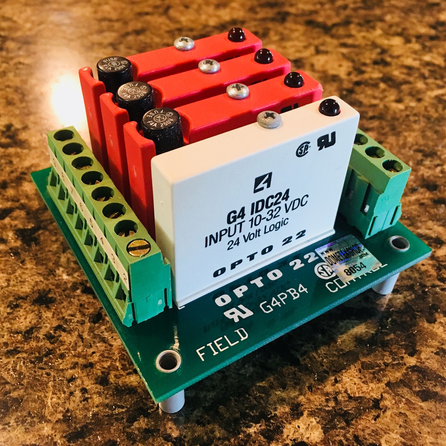
Attachments:
Last edit: 27 Apr 2019 00:20 by JTknives.
Please Log in or Create an account to join the conversation.
- rodw
-
- Offline
- Platinum Member
-
Less
More
- Posts: 11953
- Thank you received: 4070
27 Apr 2019 03:36 #132055
by rodw
Replied by rodw on topic Inputs & outputs & relays ohmic
Thats Crazy! We would pay close to $200 for something like that!
Please Log in or Create an account to join the conversation.
- islander261
- Offline
- Platinum Member
-
Less
More
- Posts: 757
- Thank you received: 216
27 Apr 2019 03:42 #132056
by islander261
Replied by islander261 on topic Inputs & outputs & relays ohmic
Prefect!
John
John
Please Log in or Create an account to join the conversation.
- JTknives
-
Topic Author
- Offline
- Elite Member
-
Less
More
- Posts: 243
- Thank you received: 32
27 Apr 2019 22:03 #132127
by JTknives
Replied by JTknives on topic Inputs & outputs & relays ohmic
So now this brings up another question. I have s THCAD10 and my hypertherm 30XP does not have a voltage devider. My plan was to put the voltage devider resistors in the plasma cutter and then run a shielded wire to the THCAD which is in my main control cabinet. Will there be problems with that plan and having the THCAD10 that far away from the source. I’m half tempted to disassemble the hand torch and build a “machine” torch out of it and tap into the start and arc voltage right at the torch head and run the wires back through the drag chain to the control cabinet. The main plasma lead will also be in the drag chain so I’m not concerned with keeping the functional hand torch feature. I’m just not a real fan of the hand torch sticking out the front or side.
On a side topic talking about THCAD10. What resistors do I need to devide the voltage down to the correct level for the THCAD10. Thanks guys
On a side topic talking about THCAD10. What resistors do I need to devide the voltage down to the correct level for the THCAD10. Thanks guys
Please Log in or Create an account to join the conversation.
- islander261
- Offline
- Platinum Member
-
Less
More
- Posts: 757
- Thank you received: 216
27 Apr 2019 22:52 #132128
by islander261
Replied by islander261 on topic Inputs & outputs & relays ohmic
Well that Opto board should take care of most of your I/O needs. Get the polarity right and one of those output blocks can be your torch on control.
The THCad 10 manual has instructions for dividing to the correct input ratio. My THCad 10 lives in a shielded box out at the plasma power supply. My home built voltage divider is on a piece of perf board inside the power supply. The voltage divider and THCad 10 want to be close together for best performance.
The way I remember HT hand torches being built I think you will be in for an ugly kludge no matter what you do. Just mount the damned thing the way everyone else does and make your connections at the power supply end of the torch lead.
John
Please Log in or Create an account to join the conversation.
- rodw
-
- Offline
- Platinum Member
-
Less
More
- Posts: 11953
- Thank you received: 4070
27 Apr 2019 23:05 - 27 Apr 2019 23:12 #132129
by rodw
Replied by rodw on topic Inputs & outputs & relays ohmic
I don't think it will matter that the resistors are located in the plasma cutter. I would just tap into the wires going to the electrode terminals inside your plasma cutter and place half the required resistance on each terminal. Most plasma cutters with a CNC post also present the raw voltage on the interface but usually have a 100k resistor on each side (which needs to be counted as part of the total THCAD resistance).
I have run raw arc voltage in my 120 amp machine with the THCAD-10 in the control panel without any problems.
I think what I'd do is mount the resitors in the plasma cutter housing and add a multi pin socket on your plasma cutter (eg CB radio microphone style) and place the THCAD-10 in a metal jiffy box like islander261 has done with an input and an output socket. You should be able to intercept the torch on signals inside the plasma cutter as well and bring them out to that port. Then steal some 5 volt power from a stepgen on your 7i76 and send that back to the jiffy box to power the THCAD.
If you want to take this one step further, mount an ACS758 current sensor on one of the electrode terminal circuits and power it from the 5 volts as well. Step the signal up to 24 volts using a LM358 low signal amplifier and connect it to an analog input on the 7i76e. That way, you will be able to pick a current threshold and synthesise your own ArcOK signal in HAL.
THe ACS758 and LM358 are available on ebay as prebuilt modules so you don't have to worry about designing a circuit! I bought thes units with the intention of doing something similar...
Last edit: 27 Apr 2019 23:12 by rodw.
Please Log in or Create an account to join the conversation.
Moderators: snowgoer540
Time to create page: 0.475 seconds