electronic tool setter, tool touch off process
- Lcvette
-

- Offline
- Moderator
-

Less
More
- Posts: 1634
- Thank you received: 763
20 Jan 2021 14:15 #195994
by Lcvette
Did it work out correctly in testing?
Replied by Lcvette on topic electronic tool setter, tool touch off process
ok This is what seems to have worked so far.
from startup:
0. home machine
1. unload spindle... Tool zero
2. touch off tool
3. input the value into spindle zero length box (red circle from your previous post).
4. load tool 99 (drewtronics probe for me)
5. touch off tool 99
6. load test file
7. run probe routine
8. load tool (it was tool 6 for me)
9. touch off tool 6
10. cycle start
for restarting the file after exit
use 6-10 steps, 4-10 if probe is not repeatable.
i will be taking some test cuts this week to prove this out fully.
Will follow up.
Did it work out correctly in testing?
Please Log in or Create an account to join the conversation.
- swalts
- Offline
- Senior Member
-

Less
More
- Posts: 65
- Thank you received: 4
24 Jan 2021 21:48 #196472
by swalts
Replied by swalts on topic electronic tool setter, tool touch off process
Lcvette:
Yes!!!! This is a successful process. I ran a test part today with very good results.
One thing I did notice though.
I flipped my part over to deck it. For this operation I was going to use the facing operation from the GUI.
During that process I switched to incremental feed and moved to my start point of the part.
the trouble came when I noticed there is no button to return to continuous feed. The AXIS GUI command is "C" for this effort. I tried hitting C and I am still in incremental feed.
Any ideas on the cause or is there a way to switch back to continuous. So far i think my option is to load AXIS gui and press C. Then close and go back to Probe Basic GUI.
Other than that, every so often I will have to switch from MAN to AUTO to regain control over my axis' movement.
As I mentioned before though. The process worked well. The part came out with beautiful results, except the decking part. I made a mess there.
The following user(s) said Thank You: Lcvette
Please Log in or Create an account to join the conversation.
- JohnnyCNC
-

- Offline
- Platinum Member
-

Less
More
- Posts: 572
- Thank you received: 115
26 Jan 2021 02:33 #196599
by JohnnyCNC
Replied by JohnnyCNC on topic electronic tool setter, tool touch off process
This thread has been a great read and will help with with my setup. I'm working on a M6 remap in QTDragon with the goal of measuring variable length tools and using the offsets in the tool table for my repeatable length tools. I use a 3D probe for work touch-offs and a fixed position tool setter for measuring the tools. I have TTS holders for all of my commonly used tools except drill bits and taps. I have the process basically working and I am just going through testing now.
Thank you both.
John
Thank you both.
John
The following user(s) said Thank You: Lcvette
Please Log in or Create an account to join the conversation.
- Lcvette
-
- Offline
- Moderator
-
Less
More
- Posts: 1634
- Thank you received: 763
26 Jan 2021 04:28 #196601
by Lcvette
swalts,
you mean the jog button is not working? hitting jog should go back to continuous movement and clicking the incremental changes over to the incremental amount.. wondering if you did not add a JOG entry in your ini file maybe? if not just add it in front of the incremental settings you have.. ie:
INCREMENTS = JOG .1in .01in .001in .0001in
this should populate a jog button next to the incremental selections! hope that helps!
Chris
Replied by Lcvette on topic electronic tool setter, tool touch off process
Lcvette:
One thing I did notice though.
I flipped my part over to deck it. For this operation I was going to use the facing operation from the GUI.
During that process I switched to incremental feed and moved to my start point of the part.
the trouble came when I noticed there is no button to return to continuous feed. The AXIS GUI command is "C" for this effort. I tried hitting C and I am still in incremental feed.
Any ideas on the cause or is there a way to switch back to continuous. So far i think my option is to load AXIS gui and press C. Then close and go back to Probe Basic GUI.
swalts,
you mean the jog button is not working? hitting jog should go back to continuous movement and clicking the incremental changes over to the incremental amount.. wondering if you did not add a JOG entry in your ini file maybe? if not just add it in front of the incremental settings you have.. ie:
INCREMENTS = JOG .1in .01in .001in .0001in
this should populate a jog button next to the incremental selections! hope that helps!
Chris
Please Log in or Create an account to join the conversation.
- swalts
- Offline
- Senior Member
-
Less
More
- Posts: 65
- Thank you received: 4
27 Jan 2021 22:44 #196839
by swalts
Replied by swalts on topic electronic tool setter, tool touch off process
Chris,
Success!!!!! add JOG to increments... so much more to learn. This was months in the making. 7i96 eth card works! tool setter...WORKS!!!, awesome probing routines...WORKS!!!, and now i can jog the machine without going back into AXIS gui...
Now I forgot the movie but... I feel like that kid standing in the middle of the room with stuff flying all around him, screaming IT'S WORKING!!! IT'S WORKING!!!
next thing to do is grab the micrometer and check my part for accuracy before i claim success...
MAN!!! what a struggle. I am going to make note of everything i did to get this machien up and running.
-Steve
The following user(s) said Thank You: tommylight
Please Log in or Create an account to join the conversation.
- Sebastianm1986
- Offline
- New Member
-

Less
More
- Posts: 2
- Thank you received: 0
07 Feb 2021 11:00 - 07 Feb 2021 11:14 #197907
by Sebastianm1986
Replied by Sebastianm1986 on topic electronic tool setter, tool touch off process
Hello, I started yesterday with Probe Basic Screen.
At first I have a spindle with no tool holders. Can anyone tell me what's the spindle zero is or how to measure the spindle zero? Is it like the TS height in the probe screen V2 by vers.by
I tried the following steps
1. Load touch probe tool 99
2. Tool touch off on the machine table (I'm using a fixed point. As I touch off the touch probe with the tool setter I can't say what's triggering first)
3. Z axis goes up to Z Homing position G53 Z0
4. In the offset page there's a positive value for TLO and a negative for current WC position (I used AXIS Gui before and the TLO is a negative number) example TLO is 130.5 and WC current position is - 130.5
4.a) Probing Z0 on my workpiece
5. Switching Tool setter position to my tool setter for example X68 Y7.5 Z0
6. Load tool 17
7. Touch off tool (Current WC position goes more in the negative direction)
Thx in advance
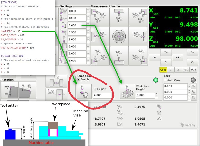
Attachments:
Last edit: 07 Feb 2021 11:14 by Sebastianm1986.
Please Log in or Create an account to join the conversation.
- andypugh
-

- Offline
- Moderator
-
Less
More
- Posts: 19879
- Thank you received: 4644
09 Feb 2021 00:00 #198101
by andypugh
Replied by andypugh on topic electronic tool setter, tool touch off process
The reference spindle zero can be anywhere. It often makes sense to use a reference tool (for example the touch probe) with a zero-length offset in the tool table, and then all the other tool lengths are relative to that.
On my mill I incorporated a tool tightening / measuring station in the table end-cover, and all tool lengths are measured from the top of the table. It's not a meaningful measure, but as long as all tools are referenced to the same point it doesn't matter.
On my mill I incorporated a tool tightening / measuring station in the table end-cover, and all tool lengths are measured from the top of the table. It's not a meaningful measure, but as long as all tools are referenced to the same point it doesn't matter.
The following user(s) said Thank You: Vector
Please Log in or Create an account to join the conversation.
- Sebastianm1986
- Offline
- New Member
-
Less
More
- Posts: 2
- Thank you received: 0
09 Feb 2021 14:59 #198149
by Sebastianm1986
Replied by Sebastianm1986 on topic electronic tool setter, tool touch off process
Hello,
I tried the following
1.Homing of machine, all Offsets are 0,spindle nose is also zero
2. load tool 100 spindle nose (touch probe in spindle)
3. tool touch off on my machine table
4. copied the probed value into spindle nose field
5. unload tool 100 and load tool 99 touch probe into the spindle (dragged it a little outside of the collet to see a difference)
6. Tool touch off probed tool offset is around 5 mm
7. Probing of Z0 on the surface of my workpiece
8. unloading tool 99 and loaded tool 17.
9. change tool touch off position to tool length switch
10. Probing
11. Going down to Z0 but the real Z0 is around 40 mm above my workpiece
Here's another way I've tried
1a. Homing and all offsets are cleared.
2. load tool 100 spindle nose and probing to my tool length sensor.
3. copied the probed value into spindle nose field.
4. unload tool 100 and load tool 99 touch probe.
5. Probing of Z0 on the surface of my workpiece
6. unloading tool 99 and loading tool 17
7. Probing of Z0 on the surface of my workpiece
8. change tool 17 and measure TLO
9. Going down to Z0 but the real Z0 is around the 2 mm above my workpiece
Please Log in or Create an account to join the conversation.
- andypugh
-
- Offline
- Moderator
-
Less
More
- Posts: 19879
- Thank you received: 4644
09 Feb 2021 23:15 #198218
by andypugh
Replied by andypugh on topic electronic tool setter, tool touch off process
Sorry, I think I have run out of help, as I don't really know what the probe screen does and I don't have a toolsetter.
Please Log in or Create an account to join the conversation.
- Lcvette
-
- Offline
- Moderator
-
Less
More
- Posts: 1634
- Thank you received: 763
18 Feb 2021 00:18 - 18 Feb 2021 00:20 #199210
by Lcvette
The spindle zero height establishes the gauge line for all other tools, i did it this way because i have run into problems in the past when measuring agains something that can/may/will change such as a probe if damaged. this way the spindle nose will always remain a constant. once that is set , using the touch probe with G43 active will correctly locate the zero height relative to the spindle nose and all tools with actual individual tool offsets will work independently of a master tool (well in essence the spindle nose becomes the master tool).
for this to work properly you need to have a z ofset length for the touch probe as well and when you use the touch probe the G43 H99 will be active and take that probe tool length into consideration when setting the zero height. so your zero height will be to the actual spindle nose and then all other tools will be good!
Hope this helps!
Chris
Replied by Lcvette on topic electronic tool setter, tool touch off process
Hello,
I tried the following
1.Homing of machine, all Offsets are 0,spindle nose is also zero
2. load tool 100 spindle nose (touch probe in spindle)
3. tool touch off on my machine table
4. copied the probed value into spindle nose field
5. unload tool 100 and load tool 99 touch probe into the spindle (dragged it a little outside of the collet to see a difference)
6. Tool touch off probed tool offset is around 5 mm
7. Probing of Z0 on the surface of my workpiece
8. unloading tool 99 and loaded tool 17.
9. change tool touch off position to tool length switch
10. Probing
11. Going down to Z0 but the real Z0 is around 40 mm above my workpiece
Here's another way I've tried
1a. Homing and all offsets are cleared.
2. load tool 100 spindle nose and probing to my tool length sensor.
3. copied the probed value into spindle nose field.
4. unload tool 100 and load tool 99 touch probe.
5. Probing of Z0 on the surface of my workpiece
6. unloading tool 99 and loading tool 17
7. Probing of Z0 on the surface of my workpiece
8. change tool 17 and measure TLO
9. Going down to Z0 but the real Z0 is around the 2 mm above my workpiece
The spindle zero height establishes the gauge line for all other tools, i did it this way because i have run into problems in the past when measuring agains something that can/may/will change such as a probe if damaged. this way the spindle nose will always remain a constant. once that is set , using the touch probe with G43 active will correctly locate the zero height relative to the spindle nose and all tools with actual individual tool offsets will work independently of a master tool (well in essence the spindle nose becomes the master tool).
for this to work properly you need to have a z ofset length for the touch probe as well and when you use the touch probe the G43 H99 will be active and take that probe tool length into consideration when setting the zero height. so your zero height will be to the actual spindle nose and then all other tools will be good!
Hope this helps!
Chris
Last edit: 18 Feb 2021 00:20 by Lcvette.
The following user(s) said Thank You: Vector
Please Log in or Create an account to join the conversation.
Moderators: KCJ, Lcvette
Time to create page: 0.119 seconds