QtDragon probing and tool touchoffs, again.....
- Roguish
-
 Topic Author
- Offline
- Elite Member
-

Less
More
- Posts: 297
- Thank you received: 31
12 Mar 2024 22:29 #295791
by Roguish
QtDragon probing and tool touchoffs, again..... was created by Roguish
Ok, i've updated once again. some nice improvements in QtDragon.
But, looking at the probing pages, i'm not sure what's up????
What's the Tool Probing page????
and how does it relate to the tool page????
I know documentation is not too fun, but it is pretty darn important.
Also, where is the arithmetic behind all the tool setting? I sure would like to see it, even if it's a scan of the back of an envelope or napkin, or something. Or, better yet, point me to the current documentation.
Attachments:
Please Log in or Create an account to join the conversation.
- cmorley
- Offline
- Moderator
-

Less
More
- Posts: 7317
- Thank you received: 2147
13 Mar 2024 00:39 #295796
by cmorley
Replied by cmorley on topic QtDragon probing and tool touchoffs, again.....
I was waiting for someone to test more:
forum.linuxcnc.org/qtvcp/51138-qtdragonh...maker-space?start=20
forum.linuxcnc.org/qtvcp/51138-qtdragonh...maker-space?start=20
The following user(s) said Thank You: Roguish
Please Log in or Create an account to join the conversation.
- Roguish
-
Topic Author
- Offline
- Elite Member
-
Less
More
- Posts: 297
- Thank you received: 31
13 Mar 2024 15:57 #295830
by Roguish
Replied by Roguish on topic QtDragon probing and tool touchoffs, again.....
I'd be happy to test it out. I just don't get how it's supposed to work.
I'm trying to get my tool setting worked out.
I purchased a tool setter and definitely want to use it.
I do not want to have everything automatic.
I prefer to set all my tools before starting to cut metal...
Like, use M6 Tx to change the tool. click a button (or run a program, even if it's in ngcgui) and have the tool Z offset set in the tool table. Use M6 Ty and repeat.
I've started an ngcgui routine, but need the arithmetic to go on.
the tool setter can also be used to determine the tool diameter.
what I've seen in the past was to rotate the tool in reverse and very slowly to a touchoff on the setter. as part of the prep, though, I think the tool setter center and diameter should be probed.
So, some additional documentation, even if it rough and prelim, would be really useful.
Then I could start testing and coding.........
Please Log in or Create an account to join the conversation.
- Odiug
- Offline
- New Member
-

Less
More
- Posts: 12
- Thank you received: 1
15 Mar 2024 20:40 #295994
by Odiug
Replied by Odiug on topic QtDragon probing and tool touchoffs, again.....
There are different approaches to realize an automatic tool length measurement. The goal is to be able to run a CNC program, which contains (manual) tool changes, where we change the tool, but afterwards, the machine does an automated measurement step. So, we are not required to touch off the zero height ourselves.
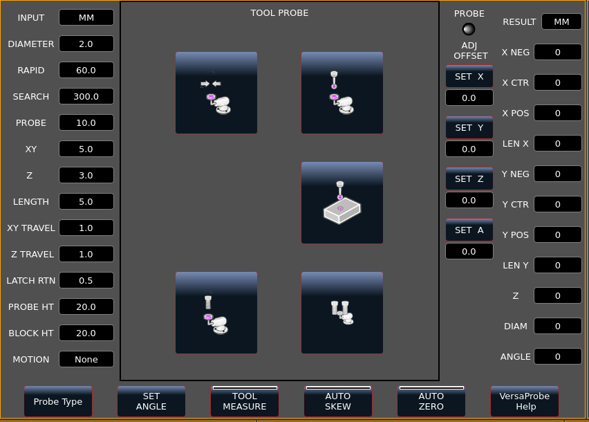
The main method QtDragon supports is the one I also know from Gmoccapy. Not sure where it was "invented". For this method you configure the tool setter height and the workpiece height in the GUI. Here: PROBE HT and BLOCK HT. Whenever a M6 Tn is encountered the remapped M6 will move the spindle to a convenient change and let you do a manual tool change. After confirming you are done, the machine will move to the tool setter and measure the new tip position. Knowing PROBE HT and BLOCK HT it will basically set the Z0 to "probed position" + BLOCK HT - PROBE HT. The tool length compensation in G-code using the entries in the tool table, is not used to my understanding.
Another method is using the tool table tool lengths entries. This is mainly used on machines having tool holders that have the actual tools attached. Different tool + holder combinations will have different length, but for one combination the length will be fixed and stay the same every time you load that combination into your spindle. You can measure the length and fill it into the tool table. When the machine does an M6 Tn tool change it knows the difference between the current tool and the new tool and will adjust the Z height accordingly.
This method can be applied to ER-collets as well, if the machine does a tool length measurement after each manual change and update the tool table for that tool. That's what I implemented with a different remap script as described in [QtDragon] Auto Tool Measurement approach and UI wishes/issues .
The method requires to load the first (or even another) tool with the M6 Tn so it does a proper tool length measurement. Then this tool can be used to touch-off Z0.
I see an advantage for the first method, when you mainly process plate material of known thickness that you always clamp to the same reference surface (the same you would use to measure the PROBE HT from). Then you just enter the known material height without further measurement and are good to go.
I personally prefer the second method, as I use a wide variety of clamping mechanisms (clamps, vices, 3-jaw chucks, ...) and different materials.
Please Log in or Create an account to join the conversation.
- cmorley
- Offline
- Moderator
-
Less
More
- Posts: 7317
- Thank you received: 2147
16 Mar 2024 01:17 #296013
by cmorley
Replied by cmorley on topic QtDragon probing and tool touchoffs, again.....
This was the rough instructions I used:
INI must have under the VERSA_TOOLSETTER heading:
X
Y
Z
MAXPROBE
Z_MAX_CLEAR
DIAMETER
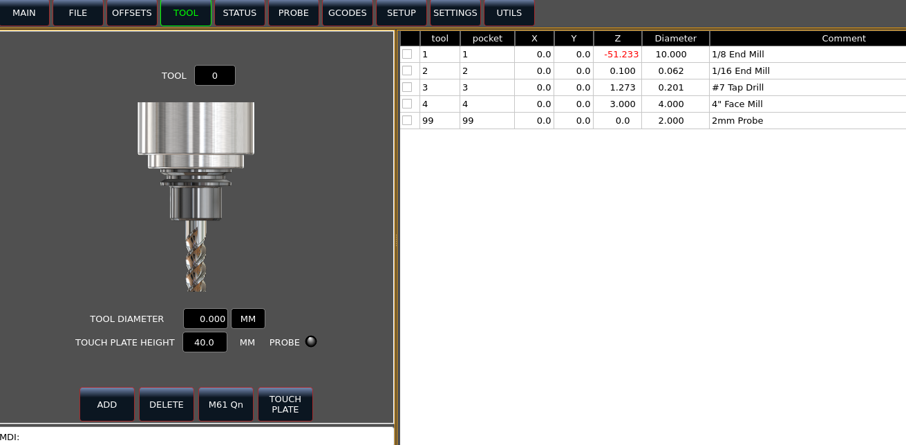
tool set probe the bare spindle with 'probe tool setter height' button. this number is without tool or user offsets.
load/call a tool in linuxcnc - jog into toolsetter position
Tool set the tool with the 'tool height of current tool' button'
tool table should update and the status tab will show the calculated offset as well as the tool setter height and raw probe results.
I loaded and tool set a couple tools.
Now I have heard of people tool setting the probe but I can't see how that can be accurate (hard to get both trip points to trip at the same time), so i did something different:
before I but the probe in, I used one of the tools I had already tool set and positioned it over my vice. I used a 1/2 diameter pin to set the height above my vice. Then I zeroed my user system (g54 in my case).
Now I installed my probe (didn't change the tool number in linuxcnc) and again used the roll pin to set the Z height of the probe on my vice. Now the Z DRO reading is the difference between the original tool length and the tool probe length. So now I take the original tool Z offset (found in the tool table) and added (subtracted? I can't remember) the DRO setting and entered that as Z for tool 99 (the probe).
Then I called up tool 99 in linuxcnc.
Not saying this is the best way - just what I did. Should only need to do this once as long as both probe lengths don't change.
I set the 'auto zero' button in versa probe and used the spindle probe to 'down z probe' the top of my vice.
Finally I changed tools back to one of the tool set tools and jogged it to the top of my vice and the dro was very close to zero.
the routine code is this:
INI must have under the VERSA_TOOLSETTER heading:
X
Y
Z
MAXPROBE
Z_MAX_CLEAR
DIAMETER
tool set probe the bare spindle with 'probe tool setter height' button. this number is without tool or user offsets.
load/call a tool in linuxcnc - jog into toolsetter position
Tool set the tool with the 'tool height of current tool' button'
tool table should update and the status tab will show the calculated offset as well as the tool setter height and raw probe results.
I loaded and tool set a couple tools.
Now I have heard of people tool setting the probe but I can't see how that can be accurate (hard to get both trip points to trip at the same time), so i did something different:
before I but the probe in, I used one of the tools I had already tool set and positioned it over my vice. I used a 1/2 diameter pin to set the height above my vice. Then I zeroed my user system (g54 in my case).
Now I installed my probe (didn't change the tool number in linuxcnc) and again used the roll pin to set the Z height of the probe on my vice. Now the Z DRO reading is the difference between the original tool length and the tool probe length. So now I take the original tool Z offset (found in the tool table) and added (subtracted? I can't remember) the DRO setting and entered that as Z for tool 99 (the probe).
Then I called up tool 99 in linuxcnc.
Not saying this is the best way - just what I did. Should only need to do this once as long as both probe lengths don't change.
I set the 'auto zero' button in versa probe and used the spindle probe to 'down z probe' the top of my vice.
Finally I changed tools back to one of the tool set tools and jogged it to the top of my vice and the dro was very close to zero.
the routine code is this:
    def probe_tool_with_toolsetter(self):
        try:
            # basic sanity checks
            for test in('ts_x','ts_y','ts_z','ts_max','ts_diam','tool_probe_height', 'tool_block_height'):
                if self['data_{}'.format(test)] is None:
                    return'Missing toolsetter setting: {}'.format(test)
            if self.data_tool_diameter is None or self.data_tool_number is None:
                return 'No tool diameter found'

            # see if we need to offset for tool diameter
            # if so see if there is enough room in X axis limits
            if self.data_tool_diameter > self.data_ts_diam:
                # if close to edge of machine X, offset in the opposite direction
                xplimit = float(INFO.INI.find('AXIS_X','MAX_LIMIT'))
                xmlimit = float(INFO.INI.find('AXIS_X','MIN_LIMIT'))
                if not (self.data_tool_diameter/2+self.data_ts_x) > xplimit:
                    Xoffset = self.data_tool_diameter/2
                elif not (self.data_ts_x -(self.data_tool_diameter/2)) < xmlimit:
                    Xoffset = 0-self.data_tool_diameter/2
                else:
                    return 'cannot offset enough in X for tool diameter'
            else: Xoffset = 0

            # offset X by tool radius (from toolfile) if required
            # probe Z
            # raise Z clear
            # move back X by tool radius if required

            cmdList = []
            cmdList.append('F{}'.format(self.data_rapid_vel))
            cmdList.append('G49')
            cmdList.append('G91')
            # should start spindle in proper direction/speed here..
            cmdList.append('G1 X{}'.format(Xoffset))
            cmdList.append('G38.2 Z-{} F{}'.format(self.data_ts_max,self.data_search_vel))
            cmdList.append('G1 Z{} F{}'.format(self.data_latch_return_dist, self.data_rapid_vel))
            cmdList.append('F{}'.format(self.data_probe_vel))
            cmdList.append('G38.2 Z-{}'.format(self.data_latch_return_dist*1.2))
            cmdList.append('#<touch_result> = #5063')
            # adjustment to G53 number
            cmdList.append('#<zworkoffset> = [#[5203 + #5220 *20] + #5213 * #5210]')
            cmdList.append('G10 L1 P#5400  Z[#5063 + #<zworkoffset> - {}]'.format( self.data_tool_probe_height))
            cmdList.append('G1 Z{} F{}'.format(self.data_z_clearance, self.data_rapid_vel))
            cmdList.append('G1 X{}'.format(-Xoffset))
            cmdList.append('G90')
            cmdList.append('G43')
            # call each command - if fail report the error and gcode command
            rtn = self.CALL_MDI_LIST(cmdList)
            if rtn != 1:
                return rtn
            h = STATUS.get_probed_position()[2]
            self.status_z = h
            p = self.data_tool_probe_height
            toffset = (h-p)
            self.add_history('''ToolSetter:
                                    Calculated Tool Length Z: {:.4f}
                                    Setter Height: {:.4f}
                                    Probed Position: {:.4f}'''.format(toffset, p, h ))
            # report success
            return 1
        except Exception as e:
            return '{}'.format(e)
The following user(s) said Thank You: Roguish
Please Log in or Create an account to join the conversation.
- cmorley
- Offline
- Moderator
-
Less
More
- Posts: 7317
- Thank you received: 2147
16 Mar 2024 01:20 - 16 Mar 2024 01:29 #296014
by cmorley
Replied by cmorley on topic QtDragon probing and tool touchoffs, again.....
I should add that this process uses the bare spindle face as the reference point for tool length.
Some people use a reference tool instead and I think you could do that with the same procedure, but I have not tried it.
Some people use a reference tool instead and I think you could do that with the same procedure, but I have not tried it.
Last edit: 16 Mar 2024 01:29 by cmorley.
The following user(s) said Thank You: Roguish
Please Log in or Create an account to join the conversation.
- cmorley
- Offline
- Moderator
-
Less
More
- Posts: 7317
- Thank you received: 2147
16 Mar 2024 01:28 #296015
by cmorley
Replied by cmorley on topic QtDragon probing and tool touchoffs, again.....
I also forgot to say the tool table must have at least a rough diameter setting for the tool to be probed. the routine will offset the tool in X axis (before probing) if the tool diameter is bigger then the tool setter diameter.
The following user(s) said Thank You: Roguish
Please Log in or Create an account to join the conversation.
- Odiug
- Offline
- New Member
-
Less
More
- Posts: 12
- Thank you received: 1
16 Mar 2024 16:12 #296071
by Odiug
Replied by Odiug on topic QtDragon probing and tool touchoffs, again.....
I am also still wondering how to use a my cheap chinese 3D probe with my DIY tool setter. The tool setter is connected to the probe input and the spindle is grounded. On contact it will pull the probe input low. For safety the tool setter surface is spring loaded and will trigger a limit switch, if case the probe failed for some reason.
I have both, 3D probe and tool setter, connected to the probe input. Now that both are spring loaded, the 3D probe only triggers after the tool setter already moved slightly. Because the 3D probe tip is isolated the tool setter cannot react to the touch of its surface.
I have seen a YT video from a company offering tool setters and 3D probes, where the tool setter had a very weak spring and reacted with a first switch (optical) for the tool measurement and had a second for over travel protection. Here the 3D probe could easily push down the tool setter to do the length measurement.
Maybe I go the other way and make the tool setter stiffer, so that the 3D probe is triggered first without pushing down the tool setter. But I am worried if a small tool (0.6mm single flute end mill) will survive the impact into a stiff tool setter at 200mm/min.
Hmmm, makes me think, that I could lower the search velocity depending on tool diameter.
Please Log in or Create an account to join the conversation.
- Hendrixx
- Offline
- Junior Member
-

Less
More
- Posts: 34
- Thank you received: 27
18 Mar 2024 15:08 #296210
by Hendrixx
Replied by Hendrixx on topic QtDragon probing and tool touchoffs, again.....
I used THCAD-2 and hyper-sensing from plasmac wired the 24V+ to a touch plate and the 24V- to table frame and after some and / or logic and modifying the touch-off sub routines with m64 m65 commands around the g38 commands. I have as far as I can tell one the most accurate tool height setters available that is safe for even the smallest tooling
Please Log in or Create an account to join the conversation.
- CADdy
-

- Offline
- Premium Member
-

Less
More
- Posts: 80
- Thank you received: 6
19 Mar 2024 16:18 #296331
by CADdy
Replied by CADdy on topic QtDragon probing and tool touchoffs, again.....
cmorley: is the routine code in Python?
Where must the Python-file be stored and how to call it?
Peter
Where must the Python-file be stored and how to call it?
Peter
Please Log in or Create an account to join the conversation.
Moderators: cmorley
Time to create page: 0.187 seconds