
- Posts: 350
- Thank you received: 410
Kinematic model for a 5axis mill with universal (nutating) head
- grandixximo
- Offline
- Platinum Member
-

Less
More
2 years 11 months ago #285799
by grandixximo
Replied by grandixximo on topic Kinematic model for a 5axis mill with universal (45° nutating) head
From ChatGPT an explaination of teansposed matrix

Please Log in or Create an account to join the conversation.
- Gurpreet
- Offline
- New Member
-

Less
More
- Posts: 8
- Thank you received: 1
2 years 11 months ago - 2 years 11 months ago #285875
by Gurpreet
Replied by Gurpreet on topic Kinematic model for a 5axis mill with universal (45° nutating) head
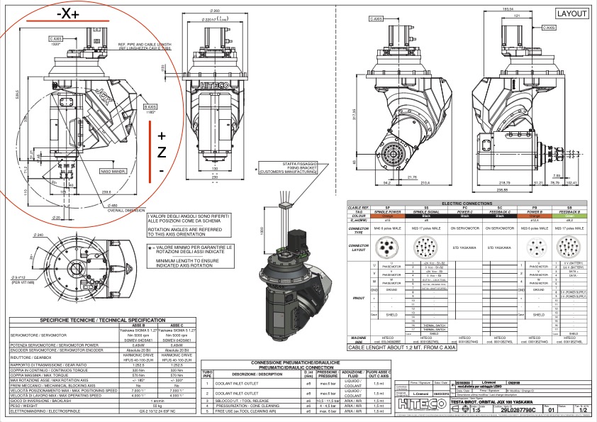
Please see attached picture for the rotary head configuration.After removing the C axis from the table side and replacing B axis with C axis on the spindle side, C axis looking good in simulation, but only when Rotary A is at home position.After changing the angle of Rotary A, TCP start to create narrow oval.Do I have to change (Rotary A) transformation matrix as well.
Last edit: 2 years 11 months ago by Gurpreet.
Please Log in or Create an account to join the conversation.
- Aciera
- Offline
- Administrator
-

Less
More
- Posts: 4819
- Thank you received: 2177
2 years 11 months ago - 2 years 11 months ago #285881
by Aciera
Replied by Aciera on topic Kinematic model for a 5axis mill with universal (45° nutating) head
I can't read the numbers in the data sheet but if your nutation axis is not 45° then you would need to change the rotation matrix for A using the formula in my documentation.
I would suggest to start with the A axis (C = 0°) and work backwards. You will also need to think about which geometrical offsets are going to be relevant in your particular assembly.
[edit]
This section is where you will need to adjust for angles other than 45°.

Note that in your case you may not be able to use a simple algebraic expression like 1 over the square root of two.
I would suggest to start with the A axis (C = 0°) and work backwards. You will also need to think about which geometrical offsets are going to be relevant in your particular assembly.
[edit]
This section is where you will need to adjust for angles other than 45°.
Note that in your case you may not be able to use a simple algebraic expression like 1 over the square root of two.
Last edit: 2 years 11 months ago by Aciera.
Please Log in or Create an account to join the conversation.
- grandixximo
- Offline
- Platinum Member
-
Less
More
- Posts: 350
- Thank you received: 410
2 years 11 months ago #285979
by grandixximo
Replied by grandixximo on topic Kinematic model for a 5axis mill with universal (45° nutating) head
He provided PDF that is readable at the end of the post, and the B axis is indeed at 50°
Please Log in or Create an account to join the conversation.
- Gurpreet
- Offline
- New Member
-
Less
More
- Posts: 8
- Thank you received: 1
2 years 11 months ago #286296
by Gurpreet
Replied by Gurpreet on topic Kinematic model for a 5axis mill with universal (45° nutating) head
Do I have to use decimal numbers or is there any other solutions?
Please Log in or Create an account to join the conversation.
- Aciera
- Offline
- Administrator
-
Less
More
- Posts: 4819
- Thank you received: 2177
2 years 11 months ago #286337
by Aciera
Replied by Aciera on topic Kinematic model for a 5axis mill with universal (45° nutating) head
I would first try using the exact algebraic expression (ie sin(50°), cos(50°)) and see what the rotation matrix looks like.
Please Log in or Create an account to join the conversation.
Time to create page: 0.159 seconds