EtherCAT plasma torch voltage reader
- rodw
-

- Away
- Platinum Member
-

Less
More
- Posts: 12012
- Thank you received: 4096
24 Feb 2025 06:41 #322461
by rodw
Replied by rodw on topic EtherCAT plasma torch voltage reader
This approach from Toast is also worth considering. As used by Swift Cut commercially (And also by Les from Sheetcam)
Please Log in or Create an account to join the conversation.
- Hakan
- Offline
- Platinum Member
-
Less
More
- Posts: 1317
- Thank you received: 453
24 Feb 2025 06:52 - 24 Feb 2025 07:35 #322464
by Hakan
Replied by Hakan on topic EtherCAT plasma torch voltage reader
@phillc54 What's the boiled down theory of that? Disconnect electrode lead and a new voltage sensor path?
Edit: looked again, no its not that. I don't get it.
Edit: looked again, no its not that. I don't get it.
Last edit: 24 Feb 2025 07:35 by Hakan.
Please Log in or Create an account to join the conversation.
- Hakan
- Offline
- Platinum Member
-
Less
More
- Posts: 1317
- Thank you received: 453
24 Feb 2025 07:42 #322468
by Hakan
Replied by Hakan on topic EtherCAT plasma torch voltage reader
For the other discussion it boils down to me realizing that I don't measure 0 to 200 Volts, but instead 0 to -200 Volts.
It works because it is truly floating, but it's not desirable the way I made it.
A quick test made me realize I am not an electronics engineer, but I'll get there. It will be put on the slow burner. I mean it works as is and it works good.
As for the grounding, it works fine so no change needed. All signals are by designed isolated, no ground loops I can think of. But if any noise problem develops, I know what you all do.
The following user(s) said Thank You: tommylight
Please Log in or Create an account to join the conversation.
- phillc54
-

- Offline
- Platinum Member
-
Less
More
- Posts: 5711
- Thank you received: 2100
24 Feb 2025 07:59 #322470
by phillc54
Replied by phillc54 on topic EtherCAT plasma torch voltage reader
Mine ended up something like this. I "think" that was my final circuit but I don't have the machine to check.
Warning: Spoiler!
Attachments:
Please Log in or Create an account to join the conversation.
- Hakan
- Offline
- Platinum Member
-
Less
More
- Posts: 1317
- Thank you received: 453
24 Feb 2025 08:20 #322471
by Hakan
Replied by Hakan on topic EtherCAT plasma torch voltage reader
But you do do that, right? Disconnect the leads to the tip and the work lead?
And then you have an electric circuit you can use for ohmic sensing. And before starting and cutting you restore the leads to the tip and the work lead.
That will work.
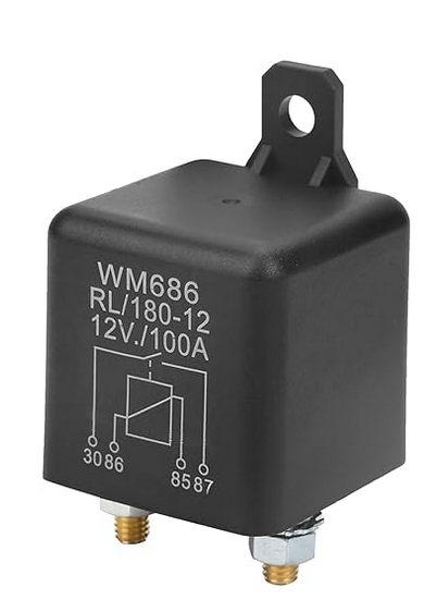
Throwing out an idea, just a simple battery disconnect relay perhaps?
And then you have an electric circuit you can use for ohmic sensing. And before starting and cutting you restore the leads to the tip and the work lead.
That will work.
Throwing out an idea, just a simple battery disconnect relay perhaps?
Attachments:
Please Log in or Create an account to join the conversation.
- RDA
- Offline
- Premium Member
-

Less
More
- Posts: 157
- Thank you received: 43
24 Feb 2025 09:18 #322474
by RDA
Replied by RDA on topic EtherCAT plasma torch voltage reader
Yeah the Hypertherm tip sensing works as the nozzle is not connected to work directly. It will only conduct to work when the IGBT connected between the nozzle-work is ”closed”. If you measure between the nozzle and work, it should read open and measuring in diode mode, it would show the IGBT in the other direction.
In the hypertherm plasma the IGBT would close only when you want to ignite, then open and have the tip ”floating”. This is what I am used to.
I never came across a plasma where the tip is connected to work as ”default”, seems it can be, and in these cases the tip sensing would not work.
In the hypertherm plasma the IGBT would close only when you want to ignite, then open and have the tip ”floating”. This is what I am used to.
I never came across a plasma where the tip is connected to work as ”default”, seems it can be, and in these cases the tip sensing would not work.
Please Log in or Create an account to join the conversation.
- RDA
- Offline
- Premium Member
-
Less
More
- Posts: 157
- Thank you received: 43
24 Feb 2025 09:21 #322475
by RDA
Replied by RDA on topic EtherCAT plasma torch voltage reader
Yeah it’s fine left floating. I tried to point out that this should not be ”expected” or ”assumed”. So anyone else trying out the pcb need to know it has to float.
I would generally not try to leave it floating as its much easier to induce accidental ground loops etc. To me atleast its much easier to properly ground everything.
I would generally not try to leave it floating as its much easier to induce accidental ground loops etc. To me atleast its much easier to properly ground everything.
Please Log in or Create an account to join the conversation.
- Hakan
- Offline
- Platinum Member
-
Less
More
- Posts: 1317
- Thank you received: 453
24 Feb 2025 10:28 #322479
by Hakan
Replied by Hakan on topic EtherCAT plasma torch voltage reader
It's much better than that. The THTIC pcb accepts floating or grounded. It only cares about the + and - leads for torch voltage, and it doesn't matter if they are already geared down to low voltage, connected to ground or to protective earth or to the electrode or anything. Below 1 kV though.
But I am looking at redesigning this.
But I am looking at redesigning this.
Please Log in or Create an account to join the conversation.
- RDA
- Offline
- Premium Member
-
Less
More
- Posts: 157
- Thank you received: 43
25 Feb 2025 14:59 #322598
by RDA
Replied by RDA on topic EtherCAT plasma torch voltage reader
Think about adding 2 resistors in series so that if one fails, the other one can still handle the voltage and power dissipation.
What I mean is to consider the risk that if R7 breaks into a short, you have the full DC going to the pcb. I would also suggest using "pulse-withstanding" resistors that are also flame proof, example something like this S5-47KF1 (yes expensive) but at least flame proof and "safety" SMF347KJT.
I think the differential approach is good vs a single ended. You might want to think about filtering the analog signal (differential and common mode), datasheet recommends LPF 10x sample rate.
Just my 2cents, if someone has better ideas or corrections I'm always happy to learn new things.
Please Log in or Create an account to join the conversation.
- Hakan
- Offline
- Platinum Member
-
Less
More
- Posts: 1317
- Thank you received: 453
26 Feb 2025 10:05 #322676
by Hakan
Replied by Hakan on topic EtherCAT plasma torch voltage reader
Thank you for looking at the design. Always good with new insights.
I can go with another resistor for added safety. Looked around a bit, and that will require a bit deeper study it look like. Not so easy to find in the sources I use. The most professional source I use is tme.eu. The only wire wound resistors at 100 kOhm they had would just fit in my hand.
Today, the resistor is chosen to operate with 500V, and 100kOhm is chosen for the heat output it generates.
I was thinking about the high voltage aspect when designing the board.
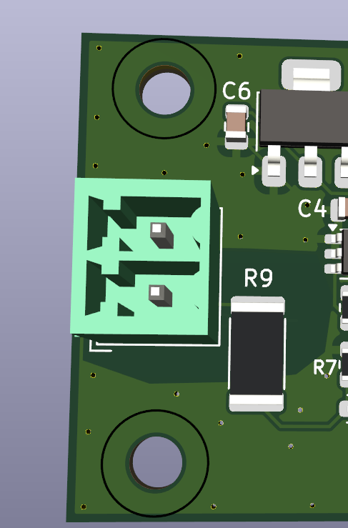
In this view you can see the short wire between the connector and the resistor. As I see it this will act as a fuse and blow out at high currents entering the board. Isolated area around the voltage parts. Hopefully any damage and malfunction will stay on the left side of the isolation barrier.
That's also why I am redesigning it.The intention was to have the ground planes electrically connected to the work piece. As it is now the ground planes are connected to the electrode. That small image is from the new design, also the high voltage part of the resistor tucked away behind the connector so shouldn't be very easy to reach with fingers.
The parts cost of one mini-board is around 10 USD/EUR so replaceable. I don't want a failure on the mini-board to break the EtherCAT board though, that's a bigger deal if that happens.
Thanks again for giving my brain some exercise.
So a new design has been made - thanks to an electronics engineer who helped - with reversed polarity for the torch voltage, well, everything is internal to the board. Should be safer, better. Just ordered new circuit boards. Somewhere after March 10th they might show up.
I can go with another resistor for added safety. Looked around a bit, and that will require a bit deeper study it look like. Not so easy to find in the sources I use. The most professional source I use is tme.eu. The only wire wound resistors at 100 kOhm they had would just fit in my hand.
Today, the resistor is chosen to operate with 500V, and 100kOhm is chosen for the heat output it generates.
I was thinking about the high voltage aspect when designing the board.
In this view you can see the short wire between the connector and the resistor. As I see it this will act as a fuse and blow out at high currents entering the board. Isolated area around the voltage parts. Hopefully any damage and malfunction will stay on the left side of the isolation barrier.
That's also why I am redesigning it.The intention was to have the ground planes electrically connected to the work piece. As it is now the ground planes are connected to the electrode. That small image is from the new design, also the high voltage part of the resistor tucked away behind the connector so shouldn't be very easy to reach with fingers.
The parts cost of one mini-board is around 10 USD/EUR so replaceable. I don't want a failure on the mini-board to break the EtherCAT board though, that's a bigger deal if that happens.
Thanks again for giving my brain some exercise.
So a new design has been made - thanks to an electronics engineer who helped - with reversed polarity for the torch voltage, well, everything is internal to the board. Should be safer, better. Just ordered new circuit boards. Somewhere after March 10th they might show up.
Attachments:
The following user(s) said Thank You: tommylight, rodw
Please Log in or Create an account to join the conversation.
Time to create page: 0.170 seconds