- Configuring LinuxCNC
- Advanced Configuration
- Servo Wiring and Tuning detailed How To example Mesa 7i77.
Servo Wiring and Tuning detailed How To example Mesa 7i77.
- Todd Zuercher
-

- Offline
- Platinum Member
-

Less
More
- Posts: 4733
- Thank you received: 1449
28 Aug 2019 12:49 #143442
by Todd Zuercher
Replied by Todd Zuercher on topic Servo Wiring and Tuning detailed How To example Mesa 7i77.
On a step/dir machine with encoder feedback, your FF1 should almost certainly be 1 assuming you started with a config made by PNCconf, and your encoder scale and stepgen scales match. You should only need to tune your P to get the best response. (Increase P until you start to see some overshoot, or instability, then back it off a little.)
If you are having a lot of trouble getting a good tune with just P, it is possible the servo drives need better tuning them selves (they have their own PID loops to tune) or the machine may have mechanical issues causing problems.
If you are having a lot of trouble getting a good tune with just P, it is possible the servo drives need better tuning them selves (they have their own PID loops to tune) or the machine may have mechanical issues causing problems.
Please Log in or Create an account to join the conversation.
- Type_Zero_Design
- Offline
- Premium Member
-

Less
More
- Posts: 133
- Thank you received: 7
28 Aug 2019 13:51 #143445
by Type_Zero_Design
Replied by Type_Zero_Design on topic Servo Wiring and Tuning detailed How To example Mesa 7i77.
Todd,
Are you suggesting that I would leave my FF1 @ 1 and then start making additional running on P. Just asking as that is the oppot of what I've been doing to this point.
Are you suggesting that I would leave my FF1 @ 1 and then start making additional running on P. Just asking as that is the oppot of what I've been doing to this point.
Please Log in or Create an account to join the conversation.
- Todd Zuercher
-
- Offline
- Platinum Member
-
Less
More
- Posts: 4733
- Thank you received: 1449
28 Aug 2019 14:35 - 28 Aug 2019 14:38 #143446
by Todd Zuercher
Replied by Todd Zuercher on topic Servo Wiring and Tuning detailed How To example Mesa 7i77.
Without seeing what the following error is doing in with a Halscope trace during a move, yes. Without seeing what is actually happening we are only guessing.
Post us a screen shot of the Halscope window showing the joint velocity command, joint velocity feedback and pid error durring a short move (all appropriately scaled so we can see them) and then we can make a good suggestion of what adjustments to make.
(There is a handy screen shot tool in the Accessories menu if you installed using a Linuxcnc iso)
Last edit: 28 Aug 2019 14:38 by Todd Zuercher.
Please Log in or Create an account to join the conversation.
- Type_Zero_Design
- Offline
- Premium Member
-
Less
More
- Posts: 133
- Thank you received: 7
28 Aug 2019 21:46 #143492
by Type_Zero_Design
Replied by Type_Zero_Design on topic Servo Wiring and Tuning detailed How To example Mesa 7i77.
Todd,
I posted a link to a video of my hall scope with the error in the post with my current settings a post back, but I know it's kind of an unconventional way to post a video so I've included it here as well( It won't let me upload directly)
photos.app.goo.gl/eiimAkZXWb9CGVqG6
Hopefully that's viewable for others, I'm not 100% sure it's from my Google drive.
Please Log in or Create an account to join the conversation.
- randypetersen
-
- Offline
- Premium Member
-
Less
More
- Posts: 136
- Thank you received: 15
29 Aug 2019 21:39 - 29 Aug 2019 21:40 #143597
by randypetersen
Replied by randypetersen on topic Servo Wiring and Tuning detailed How To example Mesa 7i77.
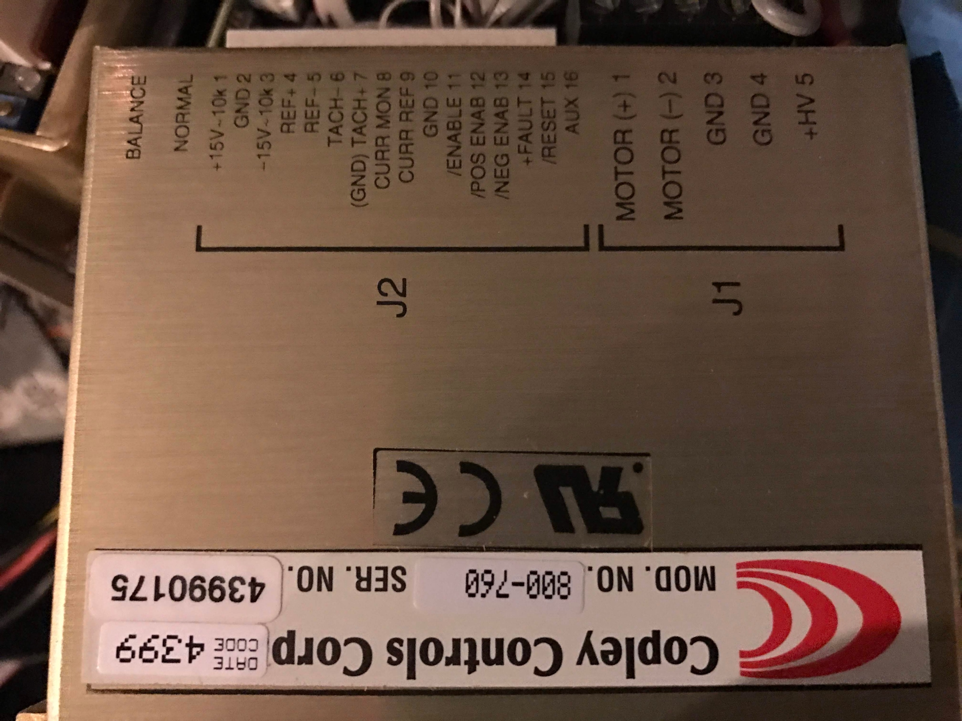
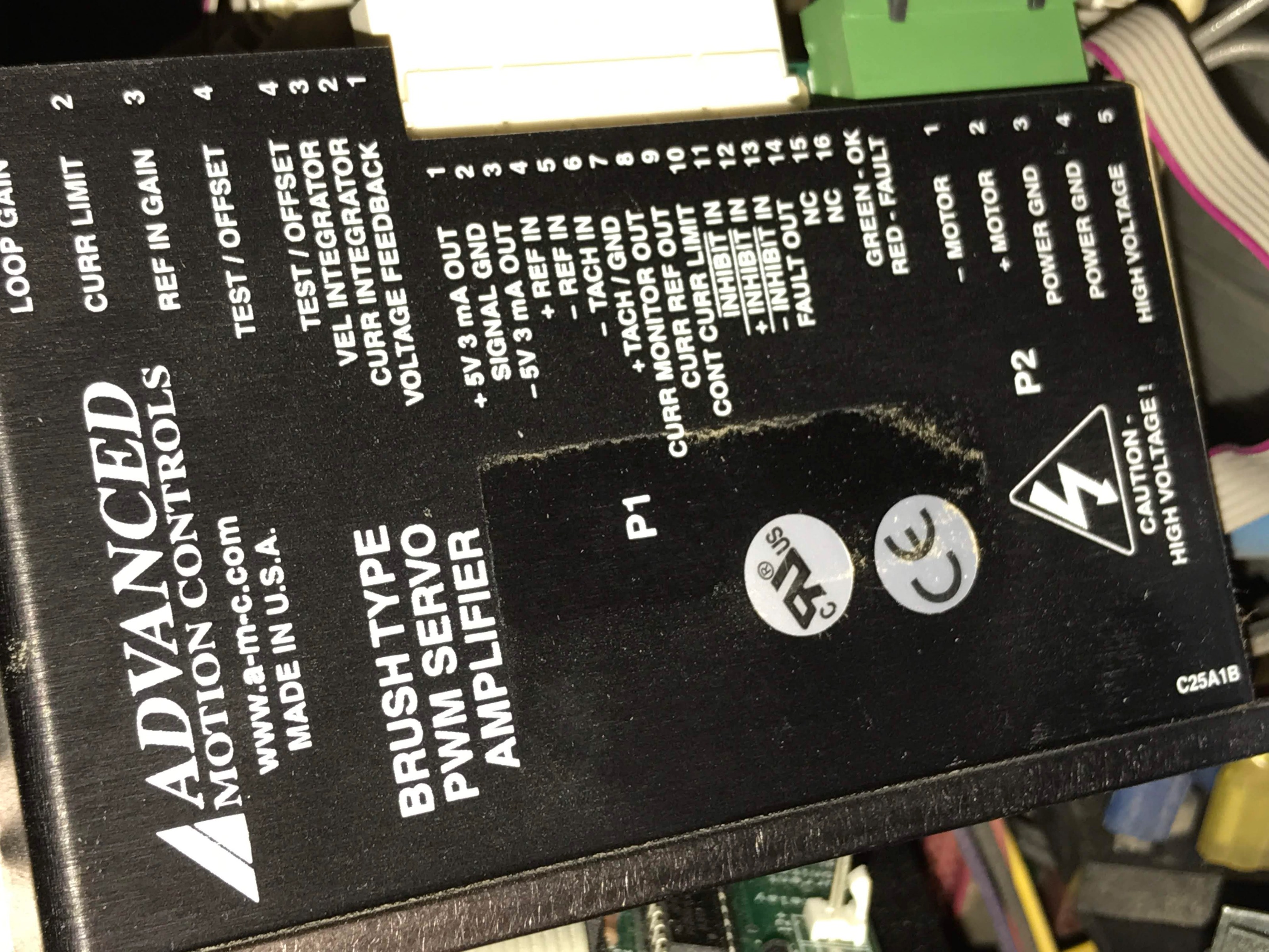
PCW, sorry to bug you again, I have looked and I can't seem to find any info on these drivers to see if they are Velocity or Torque, is there any other way to find out? Probably right in front of me.
I do think I must be doing something wrong, as the changes I make really don't make much difference. Obviously when I change the P to 500 it starts oscillating and the gantry shakes and makes some pretty loud noise, but the difference between 50 and 300 I can't really tell too much. Below 50 for P and I get following errors.
Not sure if I am not looking in the right spot or what?
Attachments:
Last edit: 29 Aug 2019 21:40 by randypetersen.
Please Log in or Create an account to join the conversation.
- PCW
-

- Offline
- Moderator
-

Less
More
- Posts: 17871
- Thank you received: 5232
29 Aug 2019 21:56 #143601
by PCW
Replied by PCW on topic Servo Wiring and Tuning detailed How To example Mesa 7i77.
1. If the drives have the tachometer connections wired, they are in velocity mode
2. Can you post your current hal/ini files
2. Can you post your current hal/ini files
Please Log in or Create an account to join the conversation.
- randypetersen
-
- Offline
- Premium Member
-
Less
More
- Posts: 136
- Thank you received: 15
29 Aug 2019 21:59 - 29 Aug 2019 22:11 #143602
by randypetersen
Replied by randypetersen on topic Servo Wiring and Tuning detailed How To example Mesa 7i77.
They are always in flux... Here they are currently.
In the file I had
#********************
# Axis X
#********************
[AXIS_0]
P = 40
That was to see how low I could go before it failed. 40 was the answer.
100 runs fine for P, but can go to 300... 400a little odd and 500 no good.
In the file I had
#********************
# Axis X
#********************
[AXIS_0]
P = 40
That was to see how low I could go before it failed. 40 was the answer.
100 runs fine for P, but can go to 300... 400a little odd and 500 no good.
Last edit: 29 Aug 2019 22:11 by randypetersen. Reason: added X P info
Please Log in or Create an account to join the conversation.
- randypetersen
-
- Offline
- Premium Member
-
Less
More
- Posts: 136
- Thank you received: 15
29 Aug 2019 22:04 #143604
by randypetersen
Replied by randypetersen on topic Servo Wiring and Tuning detailed How To example Mesa 7i77.
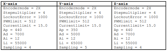
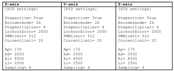
Interesting to see the tuning parameters for the same motors with different drivers and Mach3.

Please Log in or Create an account to join the conversation.
- PCW
-
- Offline
- Moderator
-
Less
More
- Posts: 17871
- Thank you received: 5232
29 Aug 2019 22:13 - 29 Aug 2019 22:14 #143607
by PCW
Replied by PCW on topic Servo Wiring and Tuning detailed How To example Mesa 7i77.
I would 1.
set all I terms to 0
set the P value low
Dial in FF1, its the most important tuning number for velocity mode drives
FF1 = 1 cannot be right unless the axis move at 10 IPS at 10V
You can also verify that the drives are operating in velocity mode
by setting the analog voltage to 0 (set P=0 in the calibrate menu)
The motors should hold position or drift slowly, and in any case resist
applied torque.
2. Do a halscope plot of commanded velocity and following error for a short move
Last edit: 29 Aug 2019 22:14 by PCW.
Please Log in or Create an account to join the conversation.
- randypetersen
-
- Offline
- Premium Member
-
Less
More
- Posts: 136
- Thank you received: 15
29 Aug 2019 22:27 - 29 Aug 2019 22:29 #143610
by randypetersen
Replied by randypetersen on topic Servo Wiring and Tuning detailed How To example Mesa 7i77.
When I set P=0 on both my X and Y they both can easily be pushed.
They come up "Joint x following error"
When they have a value, like 50, then I can not push them.
At first I thought my ferror was set to small thinking I was pushing them then triggering a joint following error and then disabling the drivers so they could move.
Was that the expected behavior? or did I screw something up.
The machine is working, it's just I have to apply very little force to the motors, or I get following errors.
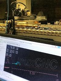
I wanted to check X and Y, since my X driver is a different brand/model than my y and z. I thought for sure that the odd driver would be the Z, because it had the brake and the screw drive. When I got the machine the odd driver " Advanced Motor Controls" was the X and the Y and Z were using the "Copley Controls" very possible I wrote that down wrong before I disassembled it.
They come up "Joint x following error"
When they have a value, like 50, then I can not push them.
At first I thought my ferror was set to small thinking I was pushing them then triggering a joint following error and then disabling the drivers so they could move.
Was that the expected behavior? or did I screw something up.
The machine is working, it's just I have to apply very little force to the motors, or I get following errors.
I wanted to check X and Y, since my X driver is a different brand/model than my y and z. I thought for sure that the odd driver would be the Z, because it had the brake and the screw drive. When I got the machine the odd driver " Advanced Motor Controls" was the X and the Y and Z were using the "Copley Controls" very possible I wrote that down wrong before I disassembled it.
Last edit: 29 Aug 2019 22:29 by randypetersen.
Please Log in or Create an account to join the conversation.
- Configuring LinuxCNC
- Advanced Configuration
- Servo Wiring and Tuning detailed How To example Mesa 7i77.
Time to create page: 0.436 seconds