- Hardware & Machines
- CNC Machines
- Milling Machines
- Prototrak Plus Retrofit with Mesa 7i77 & 5i25 cards
Prototrak Plus Retrofit with Mesa 7i77 & 5i25 cards
- andypugh
-

- Offline
- Moderator
-

- Posts: 19875
- Thank you received: 4642
Please Log in or Create an account to join the conversation.
- new2linux
- Offline
- Platinum Member
-

- Posts: 711
- Thank you received: 9
www.a-m-c.com/wp-content/uploads/support...ual_Analog_Panel.pdf
""2.2.1 Single Phase (Brushed) Servo Drives
Brushed type servo drives are designed for use with permanent magnet brushed DC motors
(PMDC motors). The drive construction is basically as shown in Figure 2.3. PMDC motors have
a single winding (armature) on the rotor, and permanent magnets on the stator (no field
winding). Brushes and commutators maintain the optimum torque angle. The torque
generated by a PMDC motor is proportional to the current, giving it excellent dynamic control
capabilities in motion control systems.
Brushed drives can also be used to control current in other inductive loads such as voice coil
actuators, magnetic bearings, etc.""
My question is can I get away with using the push together spaded connectors or do I need to start anew and make one piece, for power to servo from amp. These are to be twisted,as you see in the pic, I have shrink wrap.
many thanks!!
Please Log in or Create an account to join the conversation.
- andypugh
-
- Offline
- Moderator
-
- Posts: 19875
- Thank you received: 4642
servosystems.com/pdf/amc/12a8.pdf
I see no reason not to make new one-piece cables from the PSU to the drives, it will be a better job and the terminals are cheap. (But then I already have a good selection of crimping tools)
Please Log in or Create an account to join the conversation.
- new2linux
- Offline
- Platinum Member
-
- Posts: 711
- Thank you received: 9
EDIT: It appears the pin 1 can be used as 5v in; this can replace the separet power supply (connected to TB1) I currently have, correct?
many thanks to all!
Please Log in or Create an account to join the conversation.
- andypugh
-
- Offline
- Moderator
-
- Posts: 19875
- Thank you received: 4642
andtpugh, many thanks, I like you say need the tools, I plan to make shore the connection is tight when pushed together, then shrink tube so when twisted it is all good.
If you don't have a crimping tool then you _could_ cut off one end and do a splice, then solder and shrink-sleeve. But to be honest you are not going to get far through a retrofit without a crimping tool, and they are not all that expensive. I would, however, suggest a ratchet style one like www.amazon.com/Voilamart-Professional-In...imping/dp/B01N0Q9ZUM rather than the super-cheap ones that come with the sets.
This video shows how to make a good wire-splice.
EDIT: It appears the pin 1 can be used as 5v in; this can replace the separet power supply (connected to TB1) I currently have, correct?
Which PIN 1? Where?
Please Log in or Create an account to join the conversation.
- new2linux
- Offline
- Platinum Member
-
- Posts: 711
- Thank you received: 9
many thanks!
Please Log in or Create an account to join the conversation.
- andypugh
-
- Offline
- Moderator
-
- Posts: 19875
- Thank you received: 4642
What other power supplies do you have? You can make other voltages quite easily from 12V or 24V using these:
www.ebay.co.uk/itm/291970975595 (Item 2)
I use them a fair bit.
Please Log in or Create an account to join the conversation.
- new2linux
- Offline
- Platinum Member
-
- Posts: 711
- Thank you received: 9
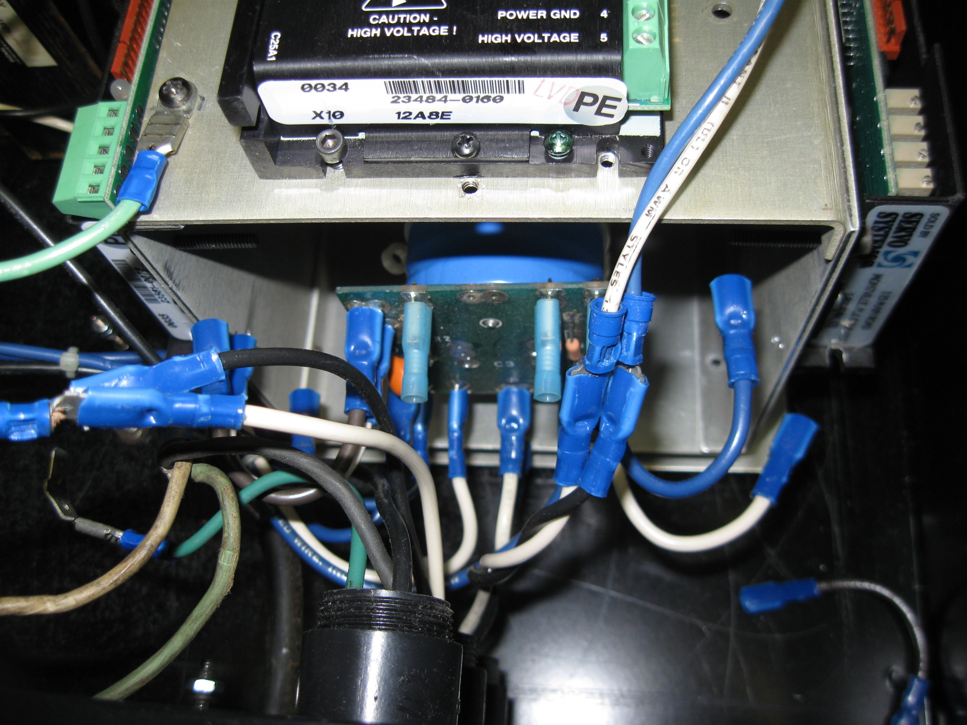
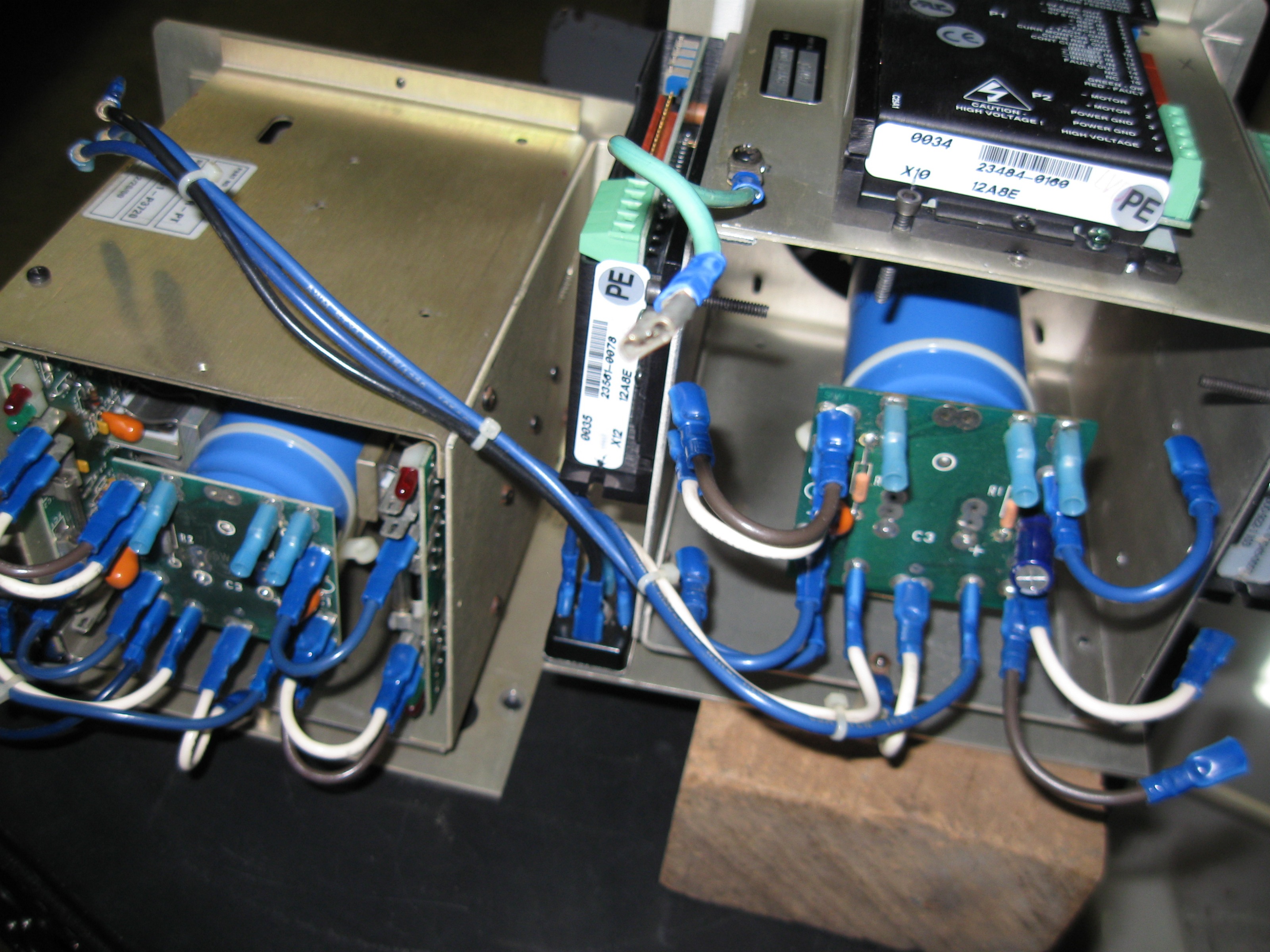
I am need to confirm leads. The pic is the end of the PCB with capacitor, the blue lead is to the right side of pic and I placed that on pin 5 on the P2 single connector (HIGH VOLTAGE DC Power Input) see this link: servosystems.com/pdf/amc/12a8.pdf.
I am attaching the white lead (the just to the left of center in the pic) to pin 4 the (POWER GND Power Ground (Common With Signal Ground))
I am attaching where the brown lead (hard to see, but is to the very far left) is to the pin 3 (POWER GND Power Ground (Common With Signal Ground)).
Now to P1 single connector: Pin 4 & Pin 5 go to 7I77 card DRV 0 & DRV 1.
Does this sound correct? Is there a way to confirm prior to powering up?
Many, many thanks in advance for help, it is warmly welcomed!
Please Log in or Create an account to join the conversation.
- lakeweb
-

- Offline
- Senior Member
-

- Posts: 56
- Thank you received: 23
I don't see any connector called DRV0 on the 7i77. The output from the 7i77 is from TB5 and called GND and AOUTx. See page 9, pdf 15 of the 7i77 manual. Those go to P1, pin 4 and 5 of the amp.
Best, Dan.
Please Log in or Create an account to join the conversation.
- andypugh
-
- Offline
- Moderator
-
- Posts: 19875
- Thank you received: 4642
I am need to confirm leads.
Yes, you do
")
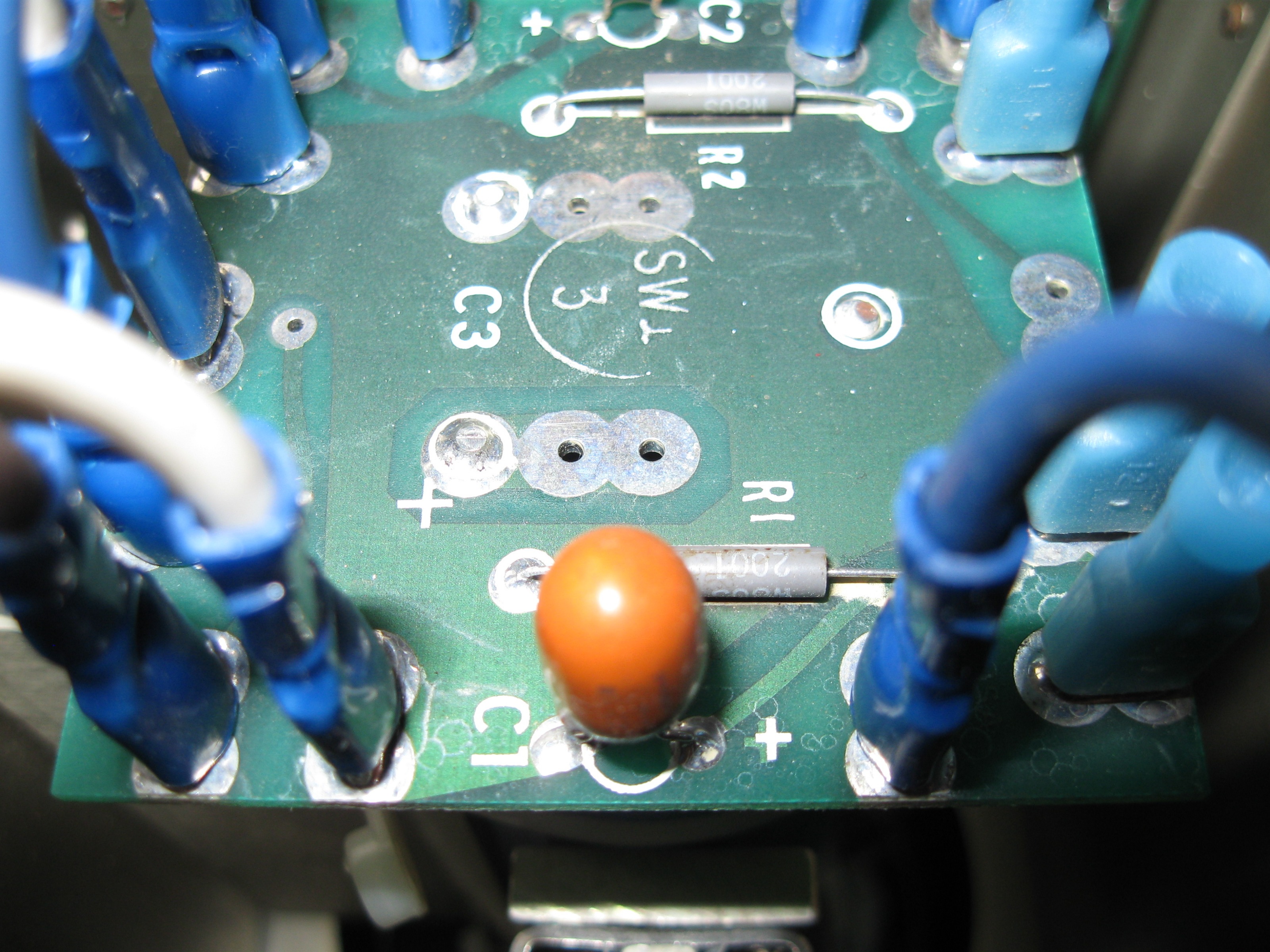
I see brown, blue and white leads. I have no idea how to tell which is which from here.
The rectifier is probably marked with + and -, as is the filter capacitor. You need to figure out which or white, blue and brown is connected to +ve and which to -ve, either by inspection of the PCB, buzzing through with a multimeter when the system is powered off (and has been for long enough to discharge the capacitor) and/or testing the voltage and polarity with the PSU powered up and no drives connected. You should also check that the voltage is no more than the 80V rating of your drives.
Please Log in or Create an account to join the conversation.
- Hardware & Machines
- CNC Machines
- Milling Machines
- Prototrak Plus Retrofit with Mesa 7i77 & 5i25 cards