Retrofitting a 1986 Maho MH400E
- RotarySMP
-
 Topic Author
- Offline
- Platinum Member
-

- Posts: 1570
- Thank you received: 576
Mark
Please Log in or Create an account to join the conversation.
- andypugh
-

- Offline
- Moderator
-

- Posts: 19804
- Thank you received: 4613
TIt is a bit weird that the cam switching blocks have 5 cams and 5 switches, but my schematic (and all other MAHO schematics I have studied) only show 4 switches being used for the feedback.
(Edit] Woops In a different part of the schematic it shows all five with the extra one being "Mitte - Vorabschaltung" Middle permature stop?
Probably 4 data channels and a "data valid" channel.
Please Log in or Create an account to join the conversation.
- RotarySMP
-
Topic Author
- Offline
- Platinum Member
-
- Posts: 1570
- Thank you received: 576
I also disconnected the CGA graphics cable (19x21). The monitor response (snow and diagonal rolling) is the same regardless whether the cable is connected or not.
I used my Multimeters frequency and oscilloscope functions to check for a H-Sync on the graphic card output. <edit> I redid the measurement with a colleauge, and there may be an H-Sync signal there. My Multimeters Osci function may just have an inadequate sample rate to confirm that.
Does anyone have a Phillips 432/10 Manual, please?
Mark
Please Log in or Create an account to join the conversation.
- drimaropoylos
- Offline
- Elite Member
-

- Posts: 265
- Thank you received: 40
Please Log in or Create an account to join the conversation.
- drimaropoylos
- Offline
- Elite Member
-
- Posts: 265
- Thank you received: 40
Please Log in or Create an account to join the conversation.
- drimaropoylos
- Offline
- Elite Member
-
- Posts: 265
- Thank you received: 40
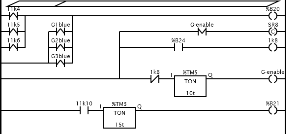
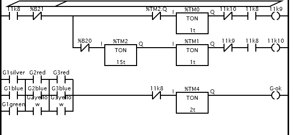
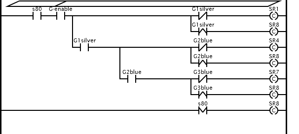
When everything is finish ok the G-ok tells the controller commanded speed is ok
The times are not tested on the machine, I will start from hi values and shorting them with tests
Please Log in or Create an account to join the conversation.
- RotarySMP
-
Topic Author
- Offline
- Platinum Member
-
- Posts: 1570
- Thank you received: 576
So far I have only read the docs on Classic Ladder, but haven't actively played around with it, so I am struggling to follow the ladder logic.
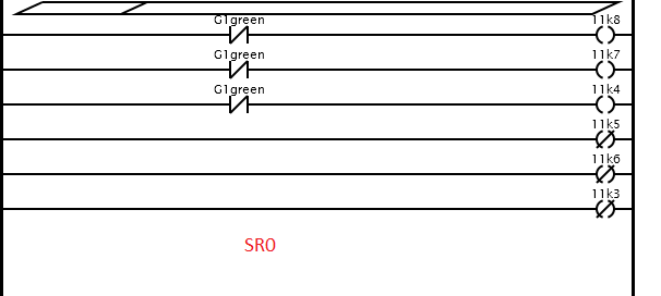
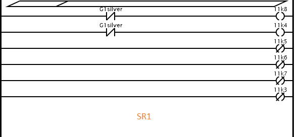
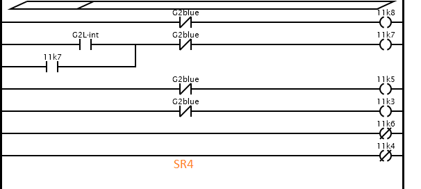
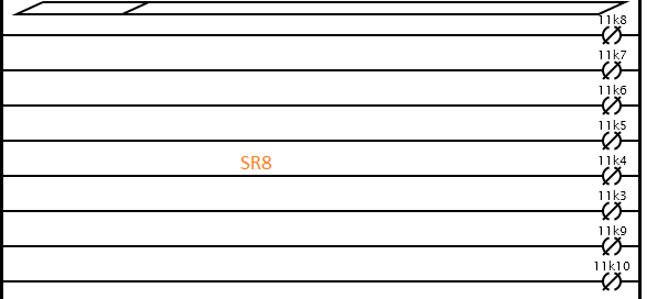
Do I understand that correctly that MAHO cam feedback switchs 11S1-5 / 11S6-10 / 11S11 -15 are assigned G[stage][color] in your Ladder? Would I be able to rename those 11S[n] to keep it consistant with my MAHO's wiring diagrams? You list five colors, but only four cams are output to the Phillips as far as I can tell.
Those fourth cam status in each group (11S4, 11S9 and 11S14) are not input to LinuxCNC through the MAHO relay board, but do connect to pins 302, 304 and 306. Does that mean that the MAHO relay board slows the motor without control input?The next cam is to slow down the motor when close to the middle gear so is not overshoot, it only works if 11k3 is enabled, so if we want to go to the middle gear we must enable the 11k3 to slow down the motor right before reaching the middle.
I got my new oscilloscope, and had another look for H-Sync and V-Sync signals out of the Phillips. Nothing. there. With the help of your Ladder, my need to get the Phillips running is diminishing. I switched to toubleshooting the E-Stop chain to see if I can find out why the Hydraulic pump doesn't start.
I am getting closer to to just removing the Phillips and going straight to LinuCNC! I started setting up the PC so I can load LinuxCNC and configure the 5i25,7i77 and 7i84. Unfortunately I am having trouble getting a bootable image on the USB stick. Last time I loaded LinuxcCNC, I used Rufus, but that program now triggers my firewalls MALWare filter. I used isotosub, but it wont boot.
I've attached the modified wiring diagrams to reflect the MESA card's replacing the Phillips 432.
Mark
Please Log in or Create an account to join the conversation.
- RotarySMP
-
Topic Author
- Offline
- Platinum Member
-
- Posts: 1570
- Thank you received: 576
There is one more I still need to do (Sheet 6) once the right way to wire the Indramats axis enable switchs becomes clear.
Mark
Please Log in or Create an account to join the conversation.
- drimaropoylos
- Offline
- Elite Member
-
- Posts: 265
- Thank you received: 40
You are right the forth cam is not connected to the controller, if 11k3 is enabled than once the forth cam is on, then the NC contact (11S4, 11S9 or 11S14) in series to the motors open and the motor gets lower voltage in series with the resistors 11r1,11r2 or 11r3
Please Log in or Create an account to join the conversation.
- drimaropoylos
- Offline
- Elite Member
-
- Posts: 265
- Thank you received: 40
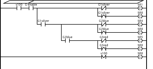
The biggest problem I had to deal with ladder is that when you enable a subroutine SR1, SR2… once you disable it (when the cam is at position), then the outputs stay on the last position they were the moment the subroutine is disabled. End when you enabled them again the items on the subroutine (timers, ext.) behave like there was no off period. I don’t know if is bug or is made to behave like this. So after a cam is at position SR8 is enabled for brief time to disable all the outputs before the next cam start to rotate.
Please Log in or Create an account to join the conversation.