Retrofitting a 1986 Maho MH400E
- drimaropoylos
- Offline
- Elite Member
-

Less
More
- Posts: 265
- Thank you received: 40
01 Oct 2017 13:33 #99731
by drimaropoylos
Replied by drimaropoylos on topic Retrofitting a 1986 Maho MH400E
Hello, there is one little problem, in LinuxCnc tb3-1…16 referred as tb3-0….15. Everything starts from 0, not from 1. I will make the configuration minus one on every contact. Can you make new drawings with the right numbers?
John
John
Please Log in or Create an account to join the conversation.
- drimaropoylos
- Offline
- Elite Member
-
Less
More
- Posts: 265
- Thank you received: 40
01 Oct 2017 13:45 #99732
by drimaropoylos
Replied by drimaropoylos on topic Retrofitting a 1986 Maho MH400E
Also on every TBX connector array there is inputs and outputs we have to name the contacts in a way that reflect the names on hall and make sure there is no chance to make mistake when wiring. Any suggestions?
Please Log in or Create an account to join the conversation.
- drimaropoylos
- Offline
- Elite Member
-
Less
More
- Posts: 265
- Thank you received: 40
01 Oct 2017 14:20 - 01 Oct 2017 14:22 #99734
by drimaropoylos
Replied by drimaropoylos on topic Retrofitting a 1986 Maho MH400E
There is one of the inputs from the cams that is going to the tb2 and all the others on tb3, can we wire them all on tb3?
John
John
Last edit: 01 Oct 2017 14:22 by drimaropoylos.
Please Log in or Create an account to join the conversation.
- RotarySMP
-
 Topic Author
- Offline
- Platinum Member
-

Less
More
- Posts: 1570
- Thank you received: 576
01 Oct 2017 18:27 - 01 Oct 2017 18:37 #99742
by RotarySMP
Replied by RotarySMP on topic Retrofitting a 1986 Maho MH400E
Evening John,
Please post some photos of your wiring.
Yes, I just assigned the the pins in the order they fell off the schematic. When I revised the schematics, there were 18 inputs from the MAHO relay board, so I couldn't get them all on one connector. Since our discusion about the "enable Axis", I see we can free up two pins by only using only one pins there, so that all the inputs could be on one connector.
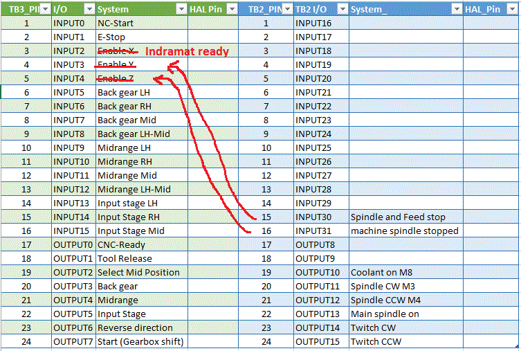
I need to revise this list and the schematic, to keep the signals in the same order as the ribbon cable. I was planning to cut the ribbon cable and split out the individual wires.
Please reassign if it makes things more practical. If you print out the wiring diagrams, write the changes on them as you install them, and then send me a scan, I can update those wiring diagrams in the PDF's.
Kind of a pain that LinuxCNC assigns the pins 0-15 where MESA names them 1-16 in there documents.I guess we could just copy the MESA doc's, and rename the pins to agree with the LinuxCNC terminology.
I have never done this before, so I don't know the best pratice in naming the signals. If we think of a signal chain, there are a lot of terms for the same signal. For example:
"Release tool"--> Relay "5K1" --> screw connection "219" --> ribbon cable "28X1-7" --> 7i84 connector "TB3-18" --> 7i84 signal name "Output 01"--> HAL name ???
Maybe Andy Pugh, or one of the more experienced guys could give us some guidance about what works well as a HAL naming convention?
Today I have been working on the EXE card shield, on planning the 3D printed parts needed to mount the ITX PSU, the hard drive, and the EXE, and on making up the 7i77 --> 7i84 RS-422 cable. I really don't understand why MESA doesn't have a matching RJ-45 connector on the 7i77 board. It is a real PITA to cut a CAT 5 cable and crimp the ferrules on those tiny wires.
Unfortunately I have no network in my basement, so I'll have to bring the whole PC and touchscreen up to the office to hang it on the network cable to install the ELO touchscreen drivers.
Mark
Please post some photos of your wiring.
Yes, I just assigned the the pins in the order they fell off the schematic. When I revised the schematics, there were 18 inputs from the MAHO relay board, so I couldn't get them all on one connector. Since our discusion about the "enable Axis", I see we can free up two pins by only using only one pins there, so that all the inputs could be on one connector.
I need to revise this list and the schematic, to keep the signals in the same order as the ribbon cable. I was planning to cut the ribbon cable and split out the individual wires.
Please reassign if it makes things more practical. If you print out the wiring diagrams, write the changes on them as you install them, and then send me a scan, I can update those wiring diagrams in the PDF's.
Kind of a pain that LinuxCNC assigns the pins 0-15 where MESA names them 1-16 in there documents.I guess we could just copy the MESA doc's, and rename the pins to agree with the LinuxCNC terminology.
I have never done this before, so I don't know the best pratice in naming the signals. If we think of a signal chain, there are a lot of terms for the same signal. For example:
"Release tool"--> Relay "5K1" --> screw connection "219" --> ribbon cable "28X1-7" --> 7i84 connector "TB3-18" --> 7i84 signal name "Output 01"--> HAL name ???
Maybe Andy Pugh, or one of the more experienced guys could give us some guidance about what works well as a HAL naming convention?
Today I have been working on the EXE card shield, on planning the 3D printed parts needed to mount the ITX PSU, the hard drive, and the EXE, and on making up the 7i77 --> 7i84 RS-422 cable. I really don't understand why MESA doesn't have a matching RJ-45 connector on the 7i77 board. It is a real PITA to cut a CAT 5 cable and crimp the ferrules on those tiny wires.
Unfortunately I have no network in my basement, so I'll have to bring the whole PC and touchscreen up to the office to hang it on the network cable to install the ELO touchscreen drivers.
Mark
Last edit: 01 Oct 2017 18:37 by RotarySMP.
Please Log in or Create an account to join the conversation.
- drimaropoylos
- Offline
- Elite Member
-
Less
More
- Posts: 265
- Thank you received: 40
01 Oct 2017 18:44 - 01 Oct 2017 18:56 #99743
by drimaropoylos
Replied by drimaropoylos on topic Retrofitting a 1986 Maho MH400E
Perfect, with excel as guide we don’t have to match the connectors to hall names. My suggestion is to keep everything related to gear change in TB3 and the rest on the relay board to TB2.
But if the order in ribbon is convenient (not entirely random) we can use this instead.
John
But if the order in ribbon is convenient (not entirely random) we can use this instead.
John
Last edit: 01 Oct 2017 18:56 by drimaropoylos.
Please Log in or Create an account to join the conversation.
- drimaropoylos
- Offline
- Elite Member
-
Less
More
- Posts: 265
- Thank you received: 40
01 Oct 2017 19:30 #99745
by drimaropoylos
Replied by drimaropoylos on topic Retrofitting a 1986 Maho MH400E
Please Log in or Create an account to join the conversation.
- RotarySMP
-
Topic Author
- Offline
- Platinum Member
-
Less
More
- Posts: 1570
- Thank you received: 576
01 Oct 2017 19:35 - 01 Oct 2017 19:39 #99746
by RotarySMP
Replied by RotarySMP on topic Retrofitting a 1986 Maho MH400E
Thanks for updating that list. Shame the forum doesn't let us post the Excel files. I aready planned a revision to that Excel file to have a colum for HAL names.
Ihave a business trip this week, with a couple of nights in a hotel, so I'll update the schematics to reflect that pin assignment.
Here is the EXE shield I made. Just some 0.75mm mild steel sheet. I would have used Aluminium, but didn't have any thin enough for my little bender.
Mark
Ihave a business trip this week, with a couple of nights in a hotel, so I'll update the schematics to reflect that pin assignment.
Here is the EXE shield I made. Just some 0.75mm mild steel sheet. I would have used Aluminium, but didn't have any thin enough for my little bender.
Mark
Last edit: 01 Oct 2017 19:39 by RotarySMP.
Please Log in or Create an account to join the conversation.
- drimaropoylos
- Offline
- Elite Member
-
Less
More
- Posts: 265
- Thank you received: 40
01 Oct 2017 19:43 #99747
by drimaropoylos
Replied by drimaropoylos on topic Retrofitting a 1986 Maho MH400E
Looks good, have a good trip.
John
John
Please Log in or Create an account to join the conversation.
- RotarySMP
-
Topic Author
- Offline
- Platinum Member
-
Less
More
- Posts: 1570
- Thank you received: 576
03 Oct 2017 19:52 #99841
by RotarySMP
Replied by RotarySMP on topic Retrofitting a 1986 Maho MH400E
The 7i77 will need an external 5V PSU due to excessive load for the PCI bus. I bought this one,
www.ebay.at/itm/Hutschienen-Netzteil-12W...6:g:LysAAOSwaeRZHVn0
and this relay for the drive enable:
www.ebay.at/itm/F3851-24-Koppel-Relais-1...a:g:vdEAAOSwhvFZBhGL
As I hope to fit both together on the free bit of DIN rail in the cabinet...here:
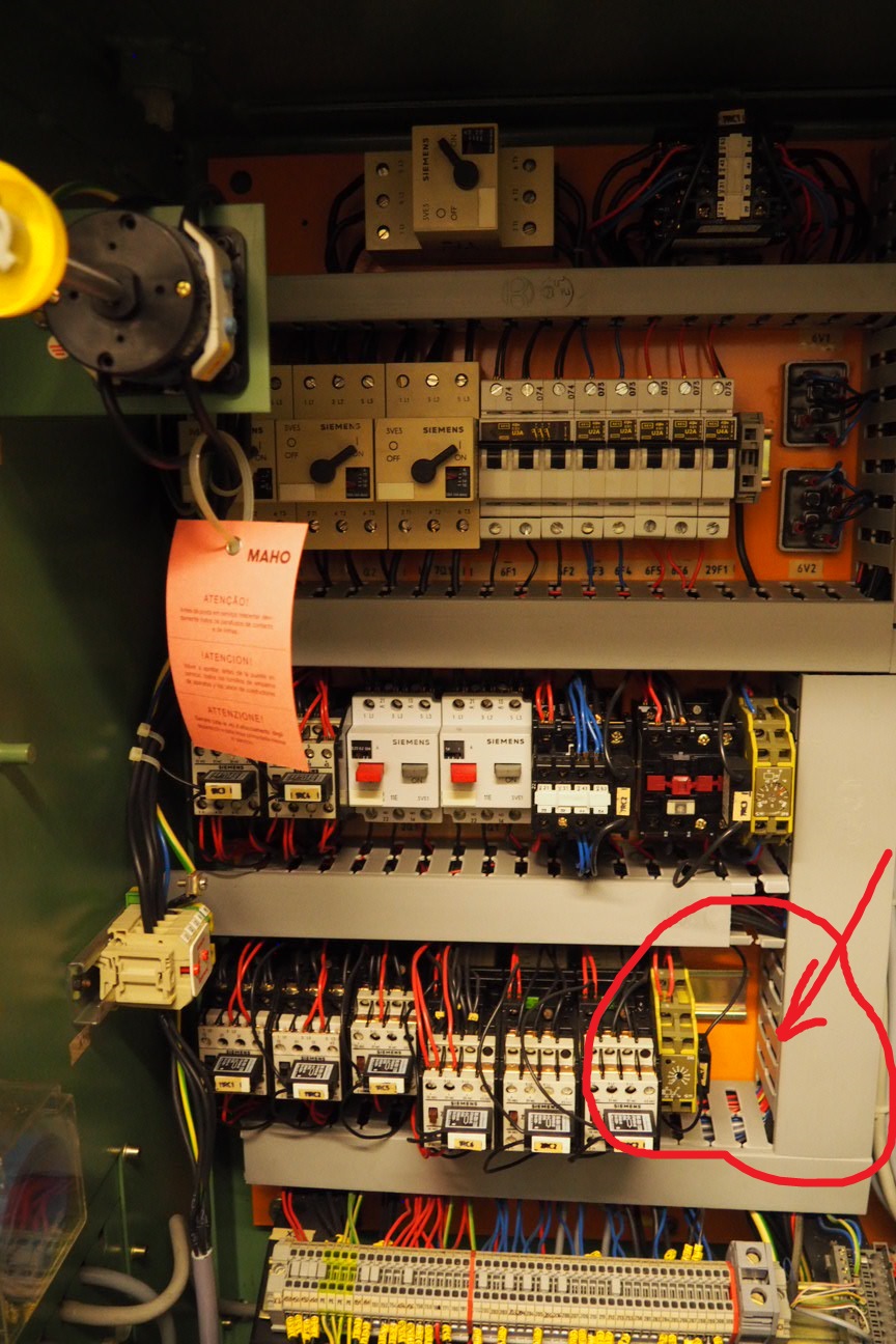
Is your electrical cabinet laid out the same?
Mark
www.ebay.at/itm/Hutschienen-Netzteil-12W...6:g:LysAAOSwaeRZHVn0
and this relay for the drive enable:
www.ebay.at/itm/F3851-24-Koppel-Relais-1...a:g:vdEAAOSwhvFZBhGL
As I hope to fit both together on the free bit of DIN rail in the cabinet...here:
Is your electrical cabinet laid out the same?
Mark
Please Log in or Create an account to join the conversation.
- RotarySMP
-
Topic Author
- Offline
- Platinum Member
-
Less
More
- Posts: 1570
- Thank you received: 576
03 Oct 2017 20:41 #99846
by RotarySMP
Replied by RotarySMP on topic Retrofitting a 1986 Maho MH400E
I just revised all the wiring diagrams to reflect all the changes we have been discussing. Please let me know if any errors have snuck in. I wired the new "Enable Drive" relay which I called 19K2, to the 7i77 rather than the 7i84, as the 7i77 will be closer to it, whereas the 7i84 I am putting on the cabinet door under the MAHO relay panel.
I am not sure whether it wouldnt be better to use one of the single axis "Drive Enable pins on 7i77 such as TB5-4, rather than a general prupose outputs like TB8-17 as I currently drew it. What is your opinion John?
Mark
I am not sure whether it wouldnt be better to use one of the single axis "Drive Enable pins on 7i77 such as TB5-4, rather than a general prupose outputs like TB8-17 as I currently drew it. What is your opinion John?
Mark
Please Log in or Create an account to join the conversation.
Moderators: piasdom
Time to create page: 0.308 seconds