Retrofitting a 1986 Maho MH400E
- RotarySMP
-
 Topic Author
- Offline
- Platinum Member
-

Less
More
- Posts: 1630
- Thank you received: 595
24 Sep 2017 16:46 #99381
by RotarySMP
Replied by RotarySMP on topic Retrofitting a 1986 Maho MH400E
I didnt pick up that SR stood for subroutine. Thanks for clarifying that Drimaropoylos. Thanks also for the explanation of the fourth CAM logic and the resisters along the top of the relay board.
I just packed up my Linux PC to bring it into a room with a LAN connection, and I will try and make a bootable LinuixCNC USB stick under linux. Once I get a more recent LinuxCNC installed (I think 2.3 is currently on it) then I can work on installing and configuring the MESA 5i25 and its two daughter boards. and start defining the HAL pins to interface with the MAHO systems. I am not yet up to the point of working on the ladder logic, but would really appreciate a copy of your files, as this logic is lot more complicated that the examples in the Ladder help files I read, so it is helpful to learn with a practical example, directly applicable to this machine. Also a copy of your HAL would really help, as I could keep the same naming convention you use.
I did some more troubleshooting on the actual machine, and for the first time noticed that all the 24V relays have a manual test button. Everyone else probably already knew that, but it was a helpful discovery for me. After using a wooden wedge to hold 19K1 on, simulating the controller ready output, I could go through and test each system. Hydraulic pump, coolant, main spindle, twitching and gearbox all seem to work. As far as I can tell so far, the only failed components in this machine are in the Phillips 432 and monitor.
Are you also using a MESA 5i25/7i77/7i84 setup, or something different? Do you have any pictures of your machine, and how you packed the replacement electronics into the electrical cabinet? Since I am going to reuse the Heindenhain EXE board, it is tempting to put the ITX motherboard, and the 7i77 onto slide in carriers, and reuse the Phillips housing. The 7i84 is going on the cabinet door, as it is only interfacing the two MAHO relay board ribbon cables (unless I run out of I/O on the 7i77).
Mark
Please Log in or Create an account to join the conversation.
- drimaropoylos
- Offline
- Elite Member
-

Less
More
- Posts: 265
- Thank you received: 40
24 Sep 2017 17:33 - 24 Sep 2017 17:35 #99383
by drimaropoylos
Replied by drimaropoylos on topic Retrofitting a 1986 Maho MH400E
Tomorrow after work, I will make a copy and post it. I constantly make changes and there are bugs and missing things. For testing on the machine disconnect everything from the mesa and keep only what you testing. The previews owners of my machine had a runaway of the servo on the Y axis, and crash it at the end of travel. The ball screw lost a lot off balls and he sold me the machine for half the price of one indramat servo.
I am using MESA 5i25/7i77
John
I am using MESA 5i25/7i77
John
Last edit: 24 Sep 2017 17:35 by drimaropoylos.
Please Log in or Create an account to join the conversation.
- RotarySMP
-
Topic Author
- Offline
- Platinum Member
-
Less
More
- Posts: 1630
- Thank you received: 595
24 Sep 2017 20:18 - 25 Sep 2017 09:30 #99385
by RotarySMP
Replied by RotarySMP on topic Retrofitting a 1986 Maho MH400E
Thanks John. Are you getting the ballscrew rebuilt or replacing it?
Do you have any Phillips 432/10 manuals? I only have the instructors examples. The one thing which I would like to know for the retrofit is what all the signals on the I/O boards 37 pin connectors 28X1 and 28X2 (The ribbon cables) are. The MAHO wiring diagram details most of the control signals which they feed to and from the Phillips, but not all.
For example, OPC1-1 (28X1-1) loops out to screw connection 208, an then back in to IPC1-2 (28X2) as "NC Start". I was just going to connect the 28x2-2 to the MESA as an output, and leave 28x1-1 disconnected.
Do you know what the BCD Zahlen {1,2,4,8,10,20,40,80} on pins OPC1-25 thru 32 are used for?
Mark
Last edit: 25 Sep 2017 09:30 by RotarySMP.
Please Log in or Create an account to join the conversation.
- drimaropoylos
- Offline
- Elite Member
-
Less
More
- Posts: 265
- Thank you received: 40
25 Sep 2017 20:23 - 25 Sep 2017 20:48 #99425
by drimaropoylos
Replied by drimaropoylos on topic Retrofitting a 1986 Maho MH400E
Hi, apparently some changes I have made on the ladder file from the windows machine conflict with the rest of the configuration and crashes. You can download the ladder for windows from here sites.google.com/site/classicladder/home/downloads to test the logic until I find the conflict and post a working configuration. You can read the files with notepad, notepad++ from windows. But don’t use the configuration file I post, I have make them for testing and is not well organized. Once installation off linuxcnc completes make a fresh start with PNCconf from the menu/linuxcnc/PNCconf linuxcnc.org/docs/html/config/pncconf.html and then make the ladder file from the start (coping the logic not the actuals values from my files).or if you complete the wiring drawing to the mesa-machine I will make the a new configuration file for our machines and post it in few days helping others in the future with complete instructions for the retrofit with drawings and configuration files.
Last edit: 25 Sep 2017 20:48 by drimaropoylos.
Please Log in or Create an account to join the conversation.
- drimaropoylos
- Offline
- Elite Member
-
Less
More
- Posts: 265
- Thank you received: 40
25 Sep 2017 20:39 #99426
by drimaropoylos
Replied by drimaropoylos on topic Retrofitting a 1986 Maho MH400E
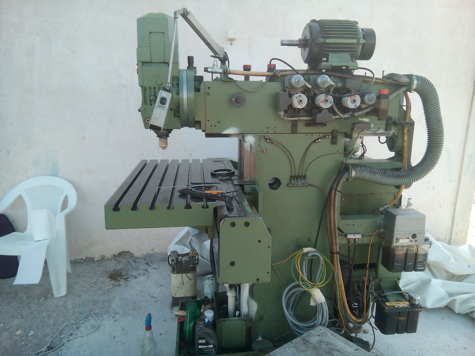
This is the machine striped. For the ballscrew, for start I have ordered balls 3.5mm g10 precision from eBay
John
John
Please Log in or Create an account to join the conversation.
- RotarySMP
-
Topic Author
- Offline
- Platinum Member
-
Less
More
- Posts: 1630
- Thank you received: 595
26 Sep 2017 09:50 - 26 Sep 2017 12:42 #99449
by RotarySMP
Replied by RotarySMP on topic Retrofitting a 1986 Maho MH400E
Hi John,
Thanks for sharing your files. Are you also planning to use Gmoccapy?
Concerning the last MAHO wiring diagram which needs modification (Sheet 06 in my set) do you have a recommendation for the axis enable set up? As far as I can tell, the three axis are enabled, and the Z motor brake released as soon as the machine is released from E-Stop (7K2 relay) or when the Z Brake release is selected on the 28A1 relay board.
LinuxCNC would normally separate these functions, first releasing the machine from E-Stop, and then enabling the drives.
Option 1
If we keep the MAHO's set up, then we need to connect the LinuxCNC "E-Stop release" button though the HAL to the MESA TB3-17 "CNC Ready" output, closing 19K1, which releases the E-Stop chain, and thus enabling all axis.
That leaves nothing for the LinuxCNC "Machine On/Enable drives" button to do.
Option 2
We add a relay between screw connection 207, and the Indramat enable pins giving LinuxCNC separate drive enable control. We will also need to move the Z brake wiring to be controlled by that same relay, otherwise we'd drop the Z axis as soon as we exit E stop, without the drive enabled.
Ideally, I'd like to use the existing relay 35K1 for this, as it was "Address M" before, and now unused. There is an input "feedback address M and T" on pin IPC1-1. I need to energise that and see if it actually controls the 35K1 relay. If the control signal to that relay is available, the second issue will be whether the relay is rated for the current of the brake, as it will be energised for hours. What is your Z brake rated at? And the final show stopper would be if the second pole of the relays is wired to ground on the PCB of the relay board. If that is the case, then I guess we will be putting an addition relay on a rail.
[edit] Option 3
Split the drive enables and wire X to the MESA 7i77 TB5-4 and Y to TB5-8. Run the Z enable and it's brake from TB5- 12 to control both the Axis enable and release the brake. This would take three relays to use the existing power at screw connection 207, thus keeping the hardware E-Stop in the enable loop. All three MESA Enable pins could be connected in the HAL to the single drive enable pin. Not sure if there would be an advantage in doing this.
Really nice machine you got there. Also looks like it had an easy life.
Yesterday I got Linuxcnc 2.7.10 loaded onto the ITX PC. I set it up with a CF card instead of a hard drive, but am already regretting that. Followed the WIKI to set it with no swap drive turn off and all the cacheing to a ram drive. After installation, the security updates took forever - probably because of RAM cache and no swap. I only have 2Gb of ram. I wanted a minimum footprint controller for my lathe when I bought the CF card adaptor, but space is pretty irrelevant no I am using it on the MAHO. Since I will probably have to do a final fresh install once I the development phase is over, I'll live with it for now.
Mark
Last edit: 26 Sep 2017 12:42 by RotarySMP. Reason: Add option 3
Please Log in or Create an account to join the conversation.
- drimaropoylos
- Offline
- Elite Member
-
Less
More
- Posts: 265
- Thank you received: 40
26 Sep 2017 17:38 - 26 Sep 2017 17:48 #99472
by drimaropoylos
Replied by drimaropoylos on topic Retrofitting a 1986 Maho MH400E
Hello, I thing we should choose the split logic of linuxcnc. And the wiring should be like this if the contact can handle the current.
Gmoccapy is the prettiest, and excellent if you put hard buttons next to screen.
I think you should buy a solid state hard drive and install LinuxCnc from the start, LinuxCnc must run to the full potential to properly calibrate the closed loop.
John
Gmoccapy is the prettiest, and excellent if you put hard buttons next to screen.
I think you should buy a solid state hard drive and install LinuxCnc from the start, LinuxCnc must run to the full potential to properly calibrate the closed loop.
John
Last edit: 26 Sep 2017 17:48 by drimaropoylos.
Please Log in or Create an account to join the conversation.
- drimaropoylos
- Offline
- Elite Member
-
Less
More
- Posts: 265
- Thank you received: 40
26 Sep 2017 17:58 - 26 Sep 2017 18:00 #99474
by drimaropoylos
Replied by drimaropoylos on topic Retrofitting a 1986 Maho MH400E
Or something like this to let LinuxCnc to temporary disable the estop for max travel
Last edit: 26 Sep 2017 18:00 by drimaropoylos.
Please Log in or Create an account to join the conversation.
- drimaropoylos
- Offline
- Elite Member
-
Less
More
- Posts: 265
- Thank you received: 40
26 Sep 2017 18:35 - 26 Sep 2017 18:36 #99480
by drimaropoylos
Replied by drimaropoylos on topic Retrofitting a 1986 Maho MH400E
The relay boars for the 7s1 says break release but instead enables the drive and releases break, I am confused. What is the real use of that switch?
Last edit: 26 Sep 2017 18:36 by drimaropoylos.
Please Log in or Create an account to join the conversation.
- RotarySMP
-
Topic Author
- Offline
- Platinum Member
-
Less
More
- Posts: 1630
- Thank you received: 595
26 Sep 2017 20:10 #99489
by RotarySMP
Replied by RotarySMP on topic Retrofitting a 1986 Maho MH400E
According to the MAHO user manual, it is to release the brake so that you can manually crank the Z axis off it's end stop. Not sure how that is supposed to work, it the drive is activated to lock the motor at the same time.
That video is quite similar to the control panel I have been thinking about. I ordered a 17" touch screen today, and also want to put soft keys around the bezel. A pendant with jog wheel is also planned. I am not planning to put as many functions on buttons as they did though.
I took a look at the relay panel and wiring this evening, but doubt we can use 35K1 for that drive enable, as we will only have access to one side of the relay. The other side goes to earth on the PCB.
Setting up the MESA cards, I noticed on MAHO sheet 12, that the Phillips had three input pins for "Enable Axis X/Y/Z". It makes no sense to implement this in this way under LinuxCNC, especially since the are all active off the same signal. I would sort of understand if each Indramat channel output a separate "Channel Ready/Healthy" signal, but it does'nt. The "Indramat ready" is fedback via L4 Bb1 and Bb2, to break the "NC Ready" chain if not ready. Seems to me like feeding that signal from L4 back to LinuxCNC as "Indramat not ready" would be a better solution.
Please Log in or Create an account to join the conversation.
Moderators: piasdom
Time to create page: 0.532 seconds