
- Posts: 69
- Thank you received: 16
Retrofitting a 1986 Maho MH400E
- D Jensen
- Offline
- Senior Member
-

Less
More
1 year 10 months ago #316556
by D Jensen
Replied by D Jensen on topic Retrofitting a 1986 Maho MH400E
Just a couple more files.These are extracted from the Maho Technical manual that you can download from one of my previous links to my Google Drive.
If you just want to remove the quill it's easy to flip the vertical head on it's side as shown. It eliminates the possibility of dropping the whole thing out accidentally.
I've edited the sketch to show a trap. Mine doesn't have the bolt setup for retaining the hand wheel assembly like Marks.I don't have the "U" shaped cover shown in Marks video. Mine has 3 separate plates instead. Under the left plate there is a a tapered dowel scotch key to retain the assembly. As you can see the instructions neither show or explains this. I've added the instruction in red. The machine has these tapered dowels in quite a few other places also.
It has the same travel limiting screw, but they only mention loosening it. Better to remove it completely since you don't know how loose to clear the quill. 5 mm maybe!
The quill clamp on mine is quite different. It can be clamped in any quill position, unlike Marks which is one tooth step on the quill rack. I think both work nicely.
The heating instruction is to remove the tool clamping mechanism.is here, but it might be wise to leave the limit screw in place before you do it. I pulled the whole lot out and heated it on the bench in the vise as previously noted.
Cheers,
David


Please Log in or Create an account to join the conversation.
- D Jensen
- Offline
- Senior Member
-
Less
More
- Posts: 69
- Thank you received: 16
1 year 10 months ago #316688
by D Jensen
Replied by D Jensen on topic Retrofitting a 1986 Maho MH400E
Hi mark,
Finally got around to compressing some photos of the spindle re-grease.
4797 shows the tool retaining system with the Belleville spring stack and the hydraulic ram.
4800 shows the quill clamps. The 2 arced pieces fit in a groove in the head bore. The Kipps handle moves the collar on the bolt. There are thumbnail milled cuts in the ends of the arced pieces (4 places). The collar and the bolt head are sitting in them. So tightening the Kipps slides the collar and brings the ends of the arced pieces closer together, clamping them onto the quill.
4803 Shows the whole assembly laid out.
4805 Is one of the taper roller cages. Looks like cast aluminium with some machining.
4806 Is one of the taper roller inner races. Looks good for 4000 running hours.
4814 Is a view along the bore for the quill in the head. Odd perspective, but what you are seeing closest is the recess that the 2 clamp arcs sit in. The 2 pins fit into the thumbnail cuts to hold the other end of them so they stay immobile when the other ends are clamped. Nice piece of engineering.
4817 The bore where the handwheel assembly fits. My finger is on the tapered dowel that scotch keys the handwheel assembly in place.
4819 Is the clamping assembly for the tool holder retention. I'm guessing it's like yours. Note the slots in the male thread on the draw bar. When the grub is torqued the ball expands that thread and locks it to the female thread on the claw assembly. You can't actually adjust the assembly until it's all assembled back into the machine since you need to have the hydraulics running to put it in the "release" position.
Cheers,
David


Please Log in or Create an account to join the conversation.
- chris mcm
- Offline
- Senior Member
-
Less
More
- Posts: 52
- Thank you received: 1
1 year 7 months ago #324088
by chris mcm
Replied by chris mcm on topic Retrofitting a 1986 Maho MH400E
Hello David, Mark and others in this group
Thank you all for your input.
David it seems your machine is the same size and model as mine.
I have removed the automation from mine and it is now a manual milling machine.
I had planned to change it to linux but at my age it is too hard. My friend Brad who could have helped me, has now moved to Australia.
I changed the grease in the horizontal spindle. Since then I have been unable to use the tool changer. There seems to be an air lock in the hydraulics. This has been a problem for several years. Health issues have delayed an earlier fix.
Last week I removed the spindle and adjusted the gripper. I have a drawing of the unit but I can not see how to get at or check the spring washers. Can any one help me please.
On the Maho 700c there is what appears to be a breather or sight glass connected to the hydraulic lines from the tool changer. Could anyone advise me more. Thanks for your interest. Chris McMullen
Auckland New Zealand
Please Log in or Create an account to join the conversation.
- D Jensen
- Offline
- Senior Member
-
Less
More
- Posts: 69
- Thank you received: 16
1 year 7 months ago #324090
by D Jensen
Replied by D Jensen on topic Retrofitting a 1986 Maho MH400E
Hi Chris,
Nice to know there is another like mine in NZ. You've probably gathered I'm from NZ, but I live in Sydney NSW.
The controller on your machine is probably an old Philips one. It's probably not worth wasting time on. Better to go with Mark's effort using LinuxCNC.
Mechanically, and some electrical I can help with.
If it is like mine then the hydraulic pump runs completely by itself. No controller involved. As soon as you power up the machine you should hear it growl.
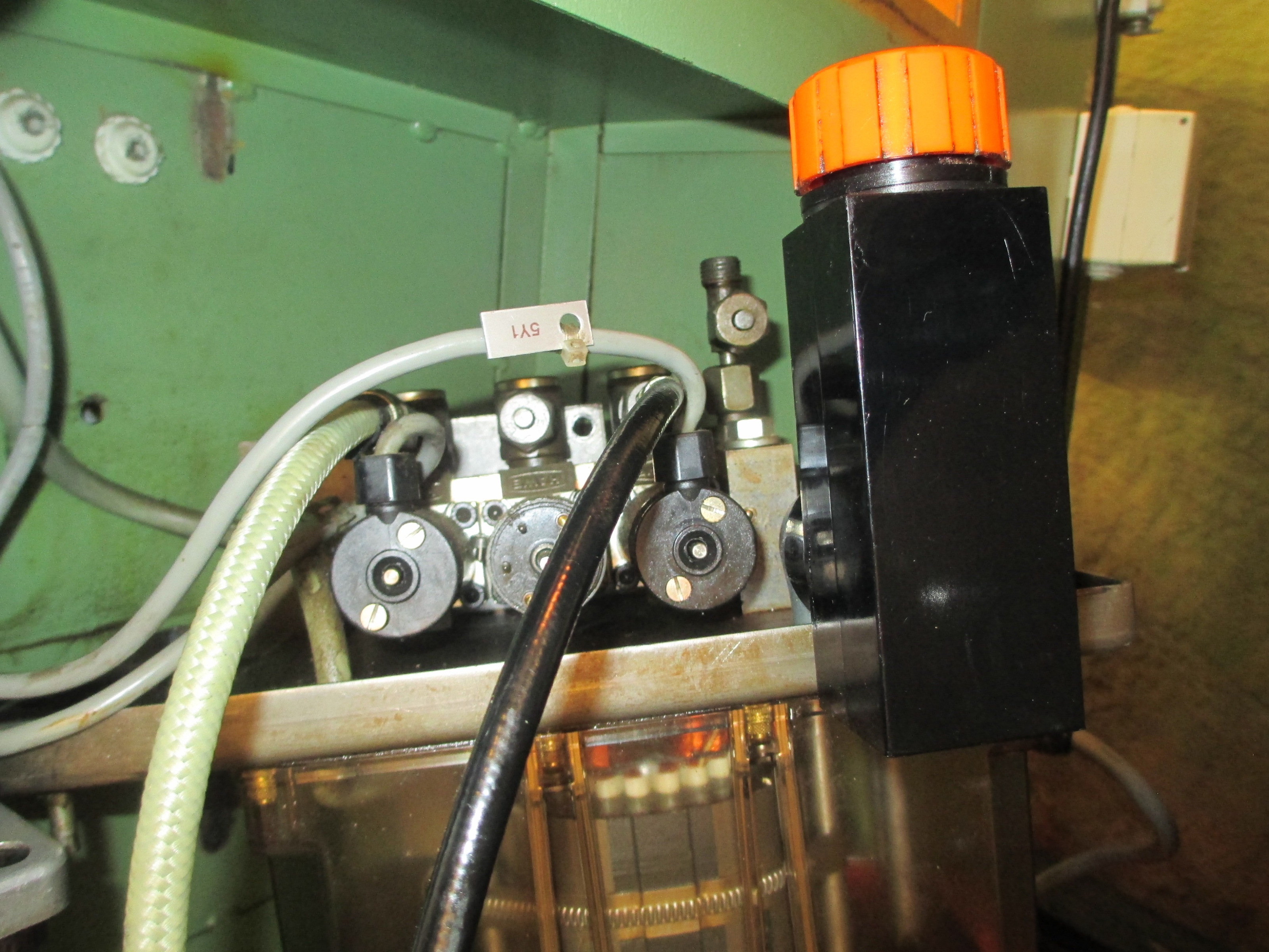
I've attached a photo of mine and a cobbled up .doc of a Hawe brochure with the data values for mine added. On mine it's running on 415 VAC. NZ and Australia use exactly the same standards.
Since it's 3 phase it needs a contactor. In my case 3K1. A very big Siemens contactor for such a small device. I think I've put my power schematic up a way back in this thread. The wiring comes directly from the Maho's main isolator switch, then through a motor starter breaker 3Q1 and then 3K1. That is the complete power wiring.
If you look at the photo I've attached you will see the hydraulic unit on mine. It's in the rear cabinet bottom door. In the photo it is half out of the cabinet so I could work on it. The 3 things on top are hydraulic solenoids. The left unclamps my rotary table. The center one isn't used and the right one with the 5Y1 tag unclamps both Z and Y spindles simultaneously. Unfortunately the pressure switch, 5K1, that operates the pump I'd removed so I could get it where it is. The pressure switch screws onto the fitting sticking up at the rear. The fitting also has a stopper plug tee'd on for a pressure gauge if you want. The pump simply runs when the pressure switch closes. The pressure switch connects to the 6V2 24VDC power supply on mine. That comes on a little later during the start sequence. Since there is no accumulator the pump will pulse on now and again very briefly, but it runs with a loud growl when you turn the switch on for tool change. Remember that the pump runs to release the tool by retracting the Belleville springs. When you release the pressure the springs pull the clamp claws back to retain the tool holder. The black hose on 5Y1 runs directly to the rotary joint on top of the Z axis. It also must get into the Y slide somehow, but I haven't looked at that.
I haven't bothered to bleed those hoses after I've had the spindle apart. My guess is they act rather like an accumulator so the pump doesn't chatter on and off. Hawe does supply the hydraulic unit with an accumulator if it's needed. Maho hasn't seen the need.
Good Luck,
David
Please Log in or Create an account to join the conversation.
- chris mcm
- Offline
- Senior Member
-
Less
More
- Posts: 52
- Thank you received: 1
1 year 7 months ago #324098
by chris mcm
Replied by chris mcm on topic Retrofitting a 1986 Maho MH400E
Written well, Thank you for your effort David
So much valuable information about The Maho 700c
I need to read this carefully
Thanks again
Chris McMullen
Auckland New Zealand
So much valuable information about The Maho 700c
I need to read this carefully
Thanks again
Chris McMullen
Auckland New Zealand
Please Log in or Create an account to join the conversation.
- D Jensen
- Offline
- Senior Member
-
Less
More
- Posts: 69
- Thank you received: 16
1 year 7 months ago #324149
by D Jensen
Replied by D Jensen on topic Retrofitting a 1986 Maho MH400E
Whoops. Big error on my part!
It's easy to forget stuff at my age. I should have checked stuff before I spouted off..
The missing pressure switch in the hydraulic in the photo is 3F1. It runs the pump directly. Otherwise the pump works as mentioned.
Contactor 5K1, which operates the tool unclamp, solenoid is part of a complex set of interlocks that stop you releasing the tool while the machine is running and stops the machine running if the tool is being changed. It also defeats the gear change jogging.
I'm not sure exactly how it works if you have the Philips controller, but I think that if you pulled any of that wiring by removing the controller the tool unclamp wont work and probably also the auto tool changer.
A lot of the interlocking is relay logic so it's probably possible to sort through the logic and strap it where the controller stuff no longer counts.
If I had an auto tool change on mine it would have been done completely on the back plane of the Heidenhain controller. But even then the relay logic would be involved and 5K1.
A key starting point is: does the hydraulic pressure pump run? It's noisy on mine. It usually runs for about 5 seconds on mine if the machine has been off for a while. On mine the light in the power button illuminates if the hydraulic pump isn't running. It's directly wired to the other contact in the 3F1 pressure switch. Seems an odd way to do it. And the bulb sometimes blows from the solenoid kick.
You will have to change gears using a spanner. On mine the half inch drive extension of a socket set works. The manual has a chart of what the coloured dots on the selector cams mean.
I think I put the logic drawing of this up earlier. It's so complex that it took me days to understand. And as you can see I often get confused by it. I went so far as to draw it in each possible state by erasing the other stuff. And even then I don't know if I got many of the possibilities.
A simple test might be to just press on the tickler on 5K1 contactor and see if the tool unclamps? Make sure to catch the tool if one is fitted.
Please Log in or Create an account to join the conversation.
Moderators: piasdom
Time to create page: 1.773 seconds