Retrofitting a 1986 Maho MH400E
- db1981
- Offline
- Platinum Member
-

- Posts: 790
- Thank you received: 276
On the MH700 the spindle is switched to star and additional the Voltage is set down.
Please Log in or Create an account to join the conversation.
- RotarySMP
-
 Topic Author
- Offline
- Platinum Member
-

- Posts: 1539
- Thank you received: 571
the png are named as the movements : L_R = Position left to Pos right switching.
links,rechts,mitte,richtung are the four cams of on transmission stage (left,right,center,an one switch witch tells the siemens plc, in which direction the motors turns last and if it has to start in opposite direction) If you start in wrong direction the motors has not enough power to lock the gear in. Also its important from the timing that the gear motor starts with the right direction from the main spindle turning.
K7Richtung, K3 Motor, Wahlmitte, Bremse are the Outputs of the PLC to the Relais. (direction Motor, Motor Power, the relais witch enable the center switch, Spindle Brake) .
Thanks for clarifying that. I didn't catch on that you only need to scope one of the three shifters as are they are all functionally the same. On my schematic, the fourth switch is not called Richtung (Direction) but Links-Mitte (Left-Mid). Instead of a stand alone PLC, the gearbox control logic is programmed into the Phillips CNC on the MH400E. I hope they didn't change the function of that fourth switch.
Do you have a photo of the physical layout of switches around the CAM from that machine? I'll pull the cover off mine to compare.
Thanks, I should have thought that through.it has to be done sequentially, otherwise if one stage is between gears then for the other stages there will be no alternating turning.
Interesting how many different ways you can accomplish a task in LinuxCNC. That Ladder, HAL or separate component all kind of tie in poularity as tools for getting this job done is suprising.
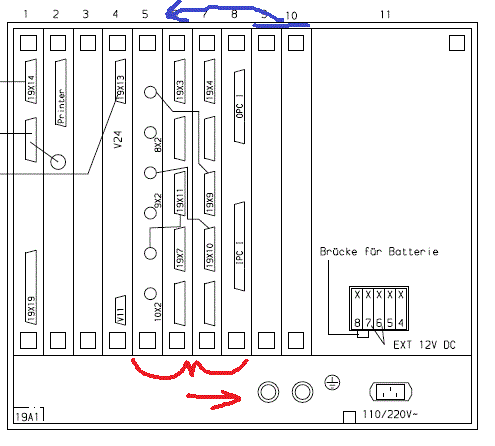
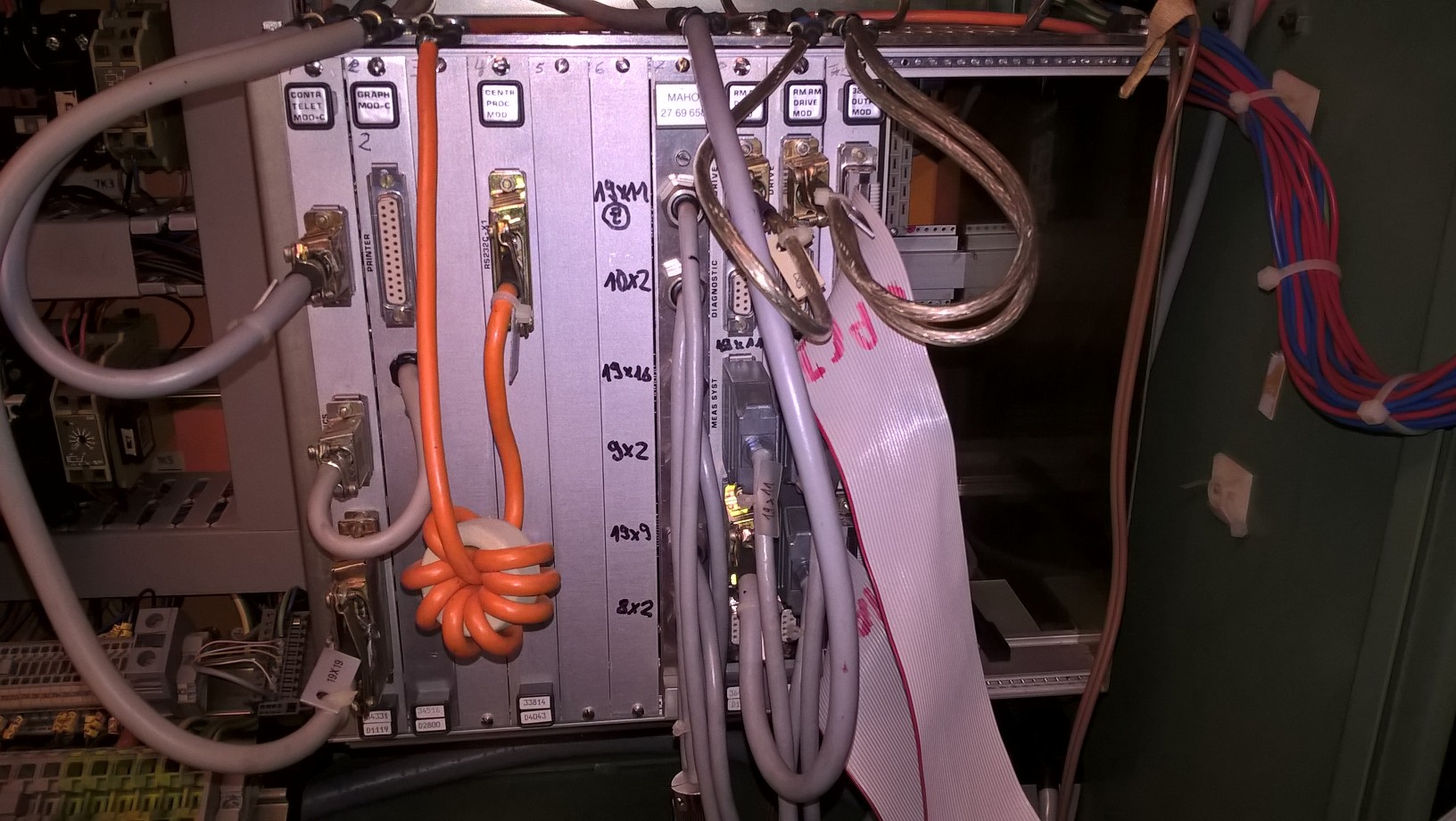
As I want to get the machine running under Phillips control before starting the retrofit, I noticed that four of the controller cards are no longer located in the same slots as when it was made. I doubted that the CNC backplane bus could deal with cards in the wrong place, and was hoping this was the reason that the Phillips 432 doesn't boot. Note, I pulled the PSU for Elko replacement.
I sent an E-Mail to DMG, and they responded that the physical location of those cards is not important. Shame, that would have been a nice obvious solution.
Mark
Please Log in or Create an account to join the conversation.
- db1981
- Offline
- Platinum Member
-

- Posts: 790
- Thank you received: 276
In 2014 i drawn a big logic diagramm to know what i have to code.
I don't know the Phillipps Control, this machine had an Heidenhain Control.
The fourth switch is originally called Links-Mitte.
Do you already have an solution for the Phillips Positions encoders?
What kind of Servo Amp is mounted in the cabinet?
Please Log in or Create an account to join the conversation.
- andypugh
-

- Offline
- Moderator
-

- Posts: 19770
- Thank you received: 4594
Interesting how many different ways you can accomplish a task in LinuxCNC. That Ladder, HAL or separate component all kind of tie in poularity as tools for getting this job done is suprising.
With the recent information that the changes need to be done in sequence I no longer favour the all-HAL approach.
If it was my machine I would be working on a custom HAL component, It seems that db1981 already has one such.
Please Log in or Create an account to join the conversation.
- RotarySMP
-
 Topic Author
- Offline
- Platinum Member
-

- Posts: 1539
- Thank you received: 571
I would love a copy of that logic diagram.In 2014 i drawn a big logic diagramm to know what i have to code.
So far I have been working through and modifying my MAHO E5170 wiring diagrams, to record all the changes that need to be made.
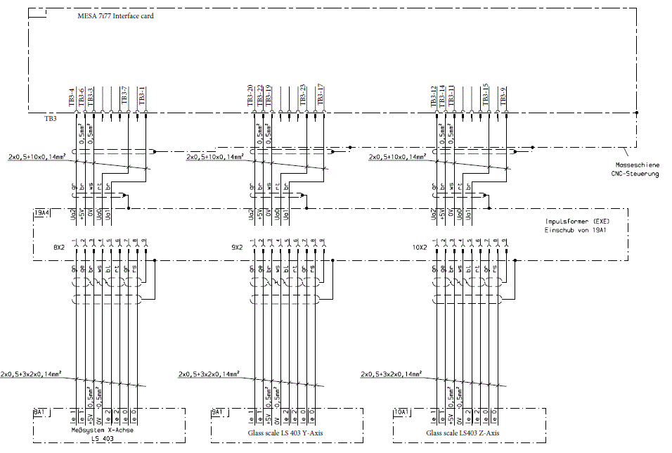
Luckily this MH400E doesn't have the Phillips glass scales. It has 11µA Heidenhain LS403's. The board in position 7 of my cabinet photo is a Heidenhain EXE which will be reused. This is the planned wiring of the scales into the 7i77.
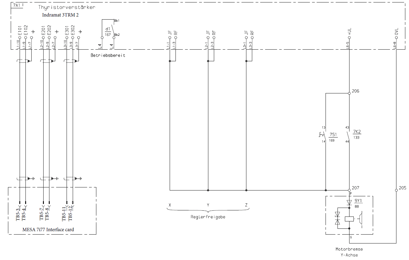
The servo amp is an Indramat 3TRM2. The +/-10V velocity command wiring looks pretty easy, but I haven't yet decide what to do with the drive enable.
Currently the Indramat releases the Z Axis brake and enables the three drive channels as soon as it is powered on, and E-Stop released. 7S1 is the switch to override the E-Stop and release the brake. It looks like the 7i77 wants to enable the drives itself, which would also be safer during the testing phase of the retrofit. I don't want that brake off before the drives are enabled. There will be at least one unused relay on the MAHO Relay board, so I could use that and let LinuxCNC have control of the Z axis brake.
Since I'm starting from zero with the Maho, and near Zero with LinuxCNC, as I am learning, I am writing a manual "How to retrofit a MAHO 400E" to capture all this information which has been so generously shared by others. Once this is done, I will post this manual, as it has been differcult to draw all the pieces of this puzzle together, and a single source would hopefully assist others in the future.
Thanks for the clarification of HAL verse component for this application Andy.
Mark
Please Log in or Create an account to join the conversation.
- RotarySMP
-
 Topic Author
- Offline
- Platinum Member
-

- Posts: 1539
- Thank you received: 571
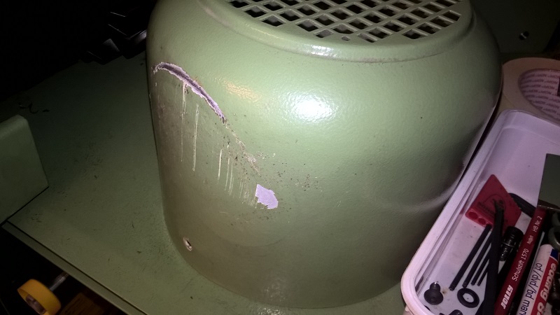
A friend beat out the dent in the spindle motor's blower shroud. Needs a little paint touch up.
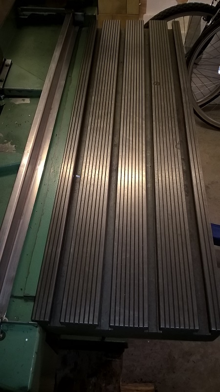
The table is back on. There are four mill scars in it.
I see back in 2012, someone set up Eagle to generate HAL files based on schematics.
wiki.linuxcnc.org/cgi-bin/wiki.pl?Eagle2HAL
Seems like a pretty cool idea. What became of it? I found no mention of it in the forum.
Mark
Please Log in or Create an account to join the conversation.
- RotarySMP
-
 Topic Author
- Offline
- Platinum Member
-

- Posts: 1539
- Thank you received: 571
Mark
Please Log in or Create an account to join the conversation.
- RotarySMP
-
 Topic Author
- Offline
- Platinum Member
-

- Posts: 1539
- Thank you received: 571
I guess technology marches on.
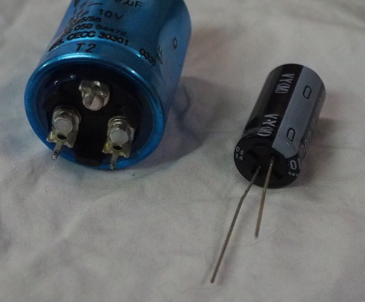
Came across this odd one in the Phillips PSU module.
It has three pins, although both the one marked T2 that to the right go into the same solder field. Is this two caps in one can, and they have only used one? Any reason not to replace it with the single cap I bought?
Mark.
Please Log in or Create an account to join the conversation.
- andypugh
-

- Offline
- Moderator
-

- Posts: 19770
- Thank you received: 4594
I would be surprised if the new cap has the same spec as the old one. Have you compared ESR?
Please Log in or Create an account to join the conversation.
- RotarySMP
-
 Topic Author
- Offline
- Platinum Member
-

- Posts: 1539
- Thank you received: 571
I am replacing the caps based on the internet wisdom that 30year old electrolytics have a good probablity of exploding whenpowered up. I bought replacements based on capacitance, voltage, tolerance and thermal limits.
I would need to know the original ESR specs for those caps, rather than their current values right? I don't have a frequency generator to supply a known AC frequency either.
Mark
Please Log in or Create an account to join the conversation.

