Retrofitting a 1986 Maho MH400E
- RotarySMP
-
 Topic Author
- Offline
- Platinum Member
-

Less
More
- Posts: 1627
- Thank you received: 595
10 Nov 2017 20:25 - 10 Nov 2017 20:28 #101629
by RotarySMP
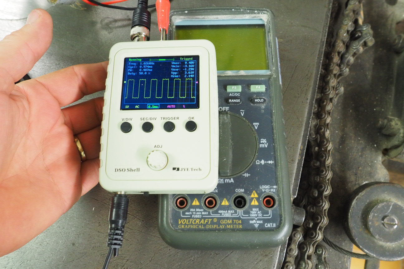
Not if your oscilloscope is a cheap chinese toy.")
I took a quick look at the 19K1 latching today.
I did this test a couple of weeks ago, jumpering between +24V on terminal 200 and terminal 209 and it worked fine...
It is weird, I have 24V output from the 7i84 for this pin, and it is activated correctly by LinuxCNC, into 28x1-2 / OPC1-2 cabe, but the relay is not closing. Checked the resistance between 209 and OPC1-2 and there is no continuaity.
We know that the Phillips standard installation wouldn't latch i if the lube oil system was low, so I am picking that the signal is passed across a couple of other relays on the 28A1 relay board on it's way in from OPC 1-2 to terminal 209. Unfortunately this is not shown on the wiring diagram, so I'd have to search for this somehow. However, to short cut the process, I wired the MESA 7i84 pin directly into the 209 terminal. Still doesn't work. I suspect the the separate 24V rails do not share a common ground.
The batteries then died on my multimeter, so I need to get some more tomorrow.
Mark
Replied by RotarySMP on topic Retrofitting a 1986 Maho MH400E
For start you can use multimeter, the oscilloscope is better but bulky.
John
Not if your oscilloscope is a cheap chinese toy.
I took a quick look at the 19K1 latching today.
I did this test a couple of weeks ago, jumpering between +24V on terminal 200 and terminal 209 and it worked fine...
It is weird, I have 24V output from the 7i84 for this pin, and it is activated correctly by LinuxCNC, into 28x1-2 / OPC1-2 cabe, but the relay is not closing. Checked the resistance between 209 and OPC1-2 and there is no continuaity.
We know that the Phillips standard installation wouldn't latch i if the lube oil system was low, so I am picking that the signal is passed across a couple of other relays on the 28A1 relay board on it's way in from OPC 1-2 to terminal 209. Unfortunately this is not shown on the wiring diagram, so I'd have to search for this somehow. However, to short cut the process, I wired the MESA 7i84 pin directly into the 209 terminal. Still doesn't work. I suspect the the separate 24V rails do not share a common ground.
The batteries then died on my multimeter, so I need to get some more tomorrow.
Mark
Last edit: 10 Nov 2017 20:28 by RotarySMP.
Please Log in or Create an account to join the conversation.
- drimaropoylos
- Offline
- Elite Member
-

Less
More
- Posts: 265
- Thank you received: 40
11 Nov 2017 15:38 #101658
by drimaropoylos
Replied by drimaropoylos on topic Retrofitting a 1986 Maho MH400E
A really handy oscilloscope. Any luck with the MahoMH600E configuration Mark?
Please Log in or Create an account to join the conversation.
- RotarySMP
-
Topic Author
- Offline
- Platinum Member
-
Less
More
- Posts: 1627
- Thank you received: 595
11 Nov 2017 16:46 - 04 Sep 2018 20:21 #101659
by RotarySMP
Replied by RotarySMP on topic Retrofitting a 1986 Maho MH400E
I pull my cover off the cover off the exe, and it seems I had the correct wiring to 0V and +5V. This voltage is also okay on the EXE test points.
My osci couldn't find any TTL output signals, or any signals at all when I moved the axis though. According to the modern EXE board connector wiring the A/B/Z signals should be on the three pins 4/5/6 (grey/blue/green).
How do I go about measuring the 11µA sine waves coming off the scales? With my multimeter on mA, its lowest scale is 400mA. Do I measure between I1+ to I1- or one pole to ground?
Something I have done has changed the DC power behavior to the relay panel. The panel receives power from all three 24V DC rails, Ignoring the third rail which is only for gearbox shifting, with terminals 201-204 energised immediately, and 201-200 energised once the estop circuit closes.
201 is the common ground between the always on rail to terminal 204, and the second rail to 201. I just measured, and the always on rail drops to 0V, as soon as the E-Stop circuit closes. I can't yet see what I screwed up to create that behavior, but am pretty sure this is causing the non-latching start problem.
**turns out it was a loose connector on the relay board**
Mark
Last edit: 04 Sep 2018 20:21 by RotarySMP.
Please Log in or Create an account to join the conversation.
- RotarySMP
-
Topic Author
- Offline
- Platinum Member
-
Less
More
- Posts: 1627
- Thank you received: 595
11 Nov 2017 17:03 #101661
by RotarySMP
I am still doing the basic wiring, and trying to get the beast to latch on, and talk with the Heidenhain glass scales. Feels like I have spend hours sitting in front of that control cabinet being very busy achieving nothing.
I haven't reloaded your latest set of config files to see if the classic Ladder file has rungs in it. thanks for the reminder.
Mark
Replied by RotarySMP on topic Retrofitting a 1986 Maho MH400E
A really handy oscilloscope. Any luck with the MahoMH600E configuration Mark?
I am still doing the basic wiring, and trying to get the beast to latch on, and talk with the Heidenhain glass scales. Feels like I have spend hours sitting in front of that control cabinet being very busy achieving nothing.
I haven't reloaded your latest set of config files to see if the classic Ladder file has rungs in it. thanks for the reminder.
Mark
Please Log in or Create an account to join the conversation.
- drimaropoylos
- Offline
- Elite Member
-
Less
More
- Posts: 265
- Thank you received: 40
11 Nov 2017 18:56 #101663
by drimaropoylos
Replied by drimaropoylos on topic Retrofitting a 1986 Maho MH400E
First check in and out voltages on the bridge rectifier 6v1 and then the transformer. But be careful, if this drop in the voltage is caused from a shortcut then there is a chance something to blowup. Disconnect one of the dc outputs of the bridge rectifier and put an amperemeter.
Please Log in or Create an account to join the conversation.
- drimaropoylos
- Offline
- Elite Member
-
Less
More
- Posts: 265
- Thank you received: 40
11 Nov 2017 19:23 - 11 Nov 2017 19:24 #101664
by drimaropoylos
Replied by drimaropoylos on topic Retrofitting a 1986 Maho MH400E
Test all the possible combination off rails and exe input to ensure the behavior is the same on all the rails and output of the exe.
Last edit: 11 Nov 2017 19:24 by drimaropoylos.
Please Log in or Create an account to join the conversation.
- andypugh
-

- Offline
- Moderator
-

Less
More
- Posts: 19875
- Thank you received: 4642
11 Nov 2017 20:45 #101665
by andypugh
I would try measuring the voltage across a load resistor.
Replied by andypugh on topic Retrofitting a 1986 Maho MH400E
How do I go about measuring the 11µA sine waves comming off the scales? With my multimeter on mA, its lowest scale is 400mA. Do I measure between I1+ to I1- or one pole to ground?
I would try measuring the voltage across a load resistor.
Please Log in or Create an account to join the conversation.
- RotarySMP
-
Topic Author
- Offline
- Platinum Member
-
Less
More
- Posts: 1627
- Thank you received: 595
12 Nov 2017 11:02 - 04 Sep 2018 20:22 #101684
by RotarySMP
Replied by RotarySMP on topic Retrofitting a 1986 Maho MH400E
Looks like I wont need to measure the 11µA sine wave at present. The EXE board also has +12V test points.
Since the MAHO wiring diagram only showed 5V supply to the glass scale EXE A/D signal processor, I wrongly figured the 12V wasn't needed. Since the MAHO wiring diagrams are wrong on the wiring colors, I connected up 12V to the test point, and sure enough,
Cool, if anyone else wants to interface Heidenhain LS403 glass scales through a 229 281 01 EXE board, the pin out is:
+12V - Red
+5V - Brown
0V - White
A - Green
B - Blue
Z - [need to confirm this, but I think it is grey.]
I'll take 12V from the ITX PSU and add terminals to wire all three EXE'S into.
Last edit: 04 Sep 2018 20:22 by RotarySMP.
Please Log in or Create an account to join the conversation.
- RotarySMP
-
Topic Author
- Offline
- Platinum Member
-
Less
More
- Posts: 1627
- Thank you received: 595
14 Nov 2017 15:40 - 14 Nov 2017 17:30 #101786
by RotarySMP
Replied by RotarySMP on topic Retrofitting a 1986 Maho MH400E
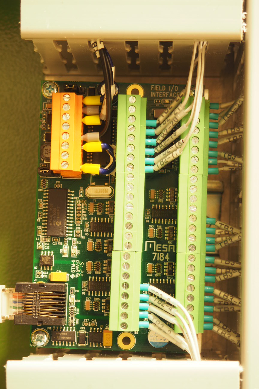
Finished wiring the MAHO 28A1 relay board I/O into the 7i84 today.
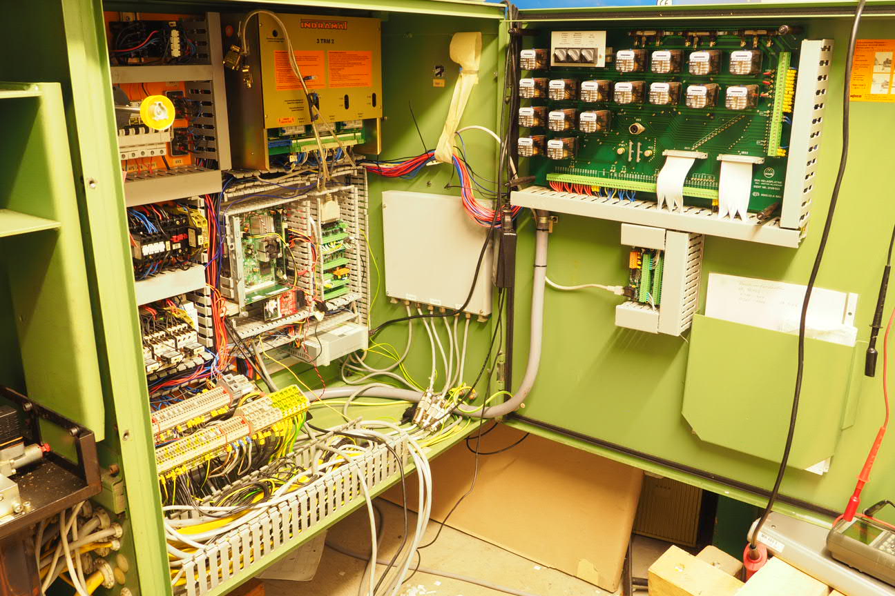
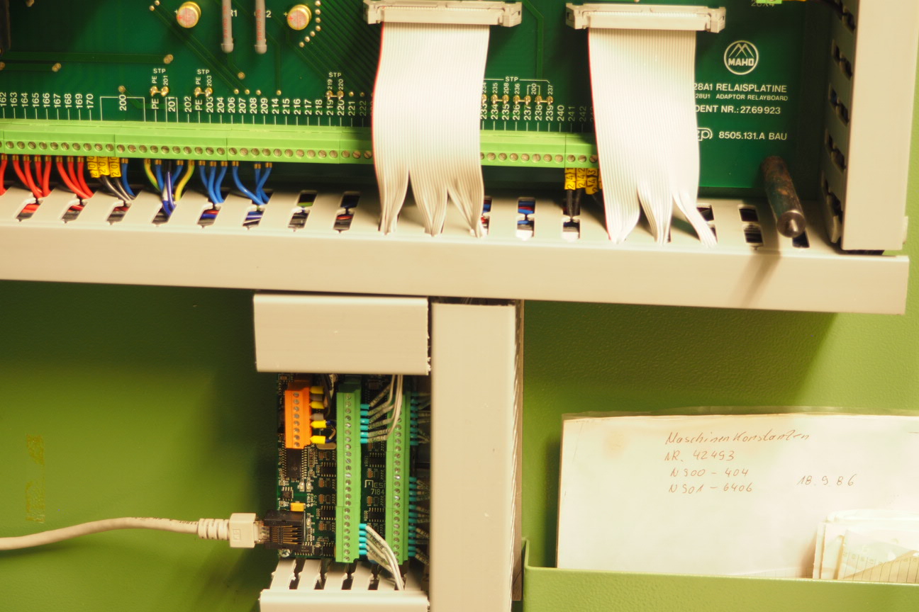
I put the E-Stop and on buttons in a temporary pendant, with a jog wheel I haven't wired up yet.
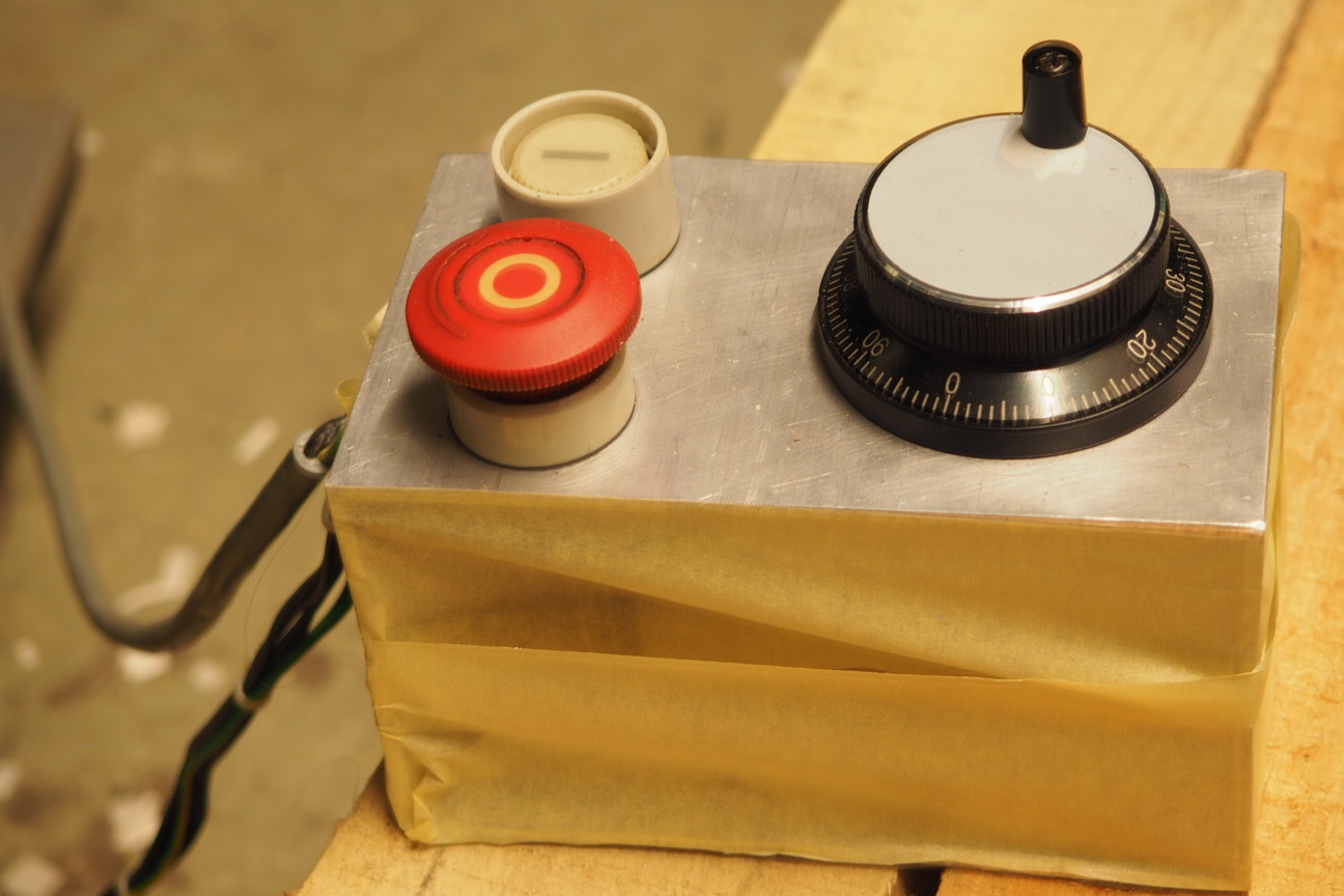
Mark
I put the E-Stop and on buttons in a temporary pendant, with a jog wheel I haven't wired up yet.
Mark
Last edit: 14 Nov 2017 17:30 by RotarySMP. Reason: Better photos
Please Log in or Create an account to join the conversation.
- tommylight
-

- Offline
- Moderator
-
Less
More
- Posts: 21700
- Thank you received: 7417
14 Nov 2017 21:57 #101801
by tommylight
Replied by tommylight on topic Retrofitting a 1986 Maho MH400E
Looks awesome for sure!
Regards,
Tom
Regards,
Tom
Please Log in or Create an account to join the conversation.
Moderators: piasdom
Time to create page: 1.939 seconds