Retrofitting a 1986 Maho MH400E
- drimaropoylos
- Offline
- Elite Member
-

Less
More
- Posts: 265
- Thank you received: 40
18 Nov 2017 10:13 #101971
by drimaropoylos
Replied by drimaropoylos on topic Retrofitting a 1986 Maho MH400E
or the test pins are not connected directly on Vcc, but a resistor is between
John
John
Please Log in or Create an account to join the conversation.
- RotarySMP
-
 Topic Author
- Offline
- Platinum Member
-

Less
More
- Posts: 1627
- Thank you received: 595
18 Nov 2017 12:34 #101972
by RotarySMP
Replied by RotarySMP on topic Retrofitting a 1986 Maho MH400E
Good inputs. Thanks. I did tie the 12V ground from the PC PSU, which is powering the EXE, to the 5V ground from the little PSU which is powering the 7i77. However, I can recheck the ground to that specific channel.
There is no resistance between the test pins and the VCC pins.
Mark
There is no resistance between the test pins and the VCC pins.
Mark
Please Log in or Create an account to join the conversation.
- tommylight
-

- Away
- Moderator
-

Less
More
- Posts: 21700
- Thank you received: 7417
19 Nov 2017 02:36 #101988
by tommylight
Replied by tommylight on topic Retrofitting a 1986 Maho MH400E
You should check if something connected to that scale is getting hot with time, like the EXE ( as far as i remember reading here ) or check for power supply ripple, but since that occurs only on one axis i doubt that would be it.
Check also if there is any possibility to measure the voltage going to the LED on that scale ( or is it a bulb ???? ), LED tend to lower the intensity as soon as they start to heat.
Check also if there is any possibility to measure the voltage going to the LED on that scale ( or is it a bulb ???? ), LED tend to lower the intensity as soon as they start to heat.
Please Log in or Create an account to join the conversation.
- RotarySMP
-
Topic Author
- Offline
- Platinum Member
-
Less
More
- Posts: 1627
- Thank you received: 595
19 Nov 2017 12:14 - 19 Nov 2017 12:23 #102004
by RotarySMP
Replied by RotarySMP on topic Retrofitting a 1986 Maho MH400E
Good inputs. Thanks.
I reterminated the two ribbon cables. Need to take a break and recheck all my work before I install them. Is there an industry standard way to terminate the unsed wire ends? I'd just neaten them up and bundle them with heatshrink.
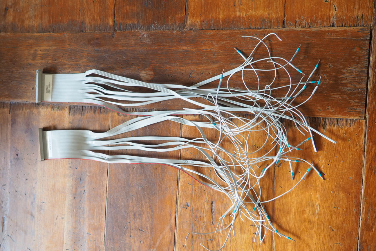
Attached are the two pin maps I have so far.
Mark
I reterminated the two ribbon cables. Need to take a break and recheck all my work before I install them. Is there an industry standard way to terminate the unsed wire ends? I'd just neaten them up and bundle them with heatshrink.
Attached are the two pin maps I have so far.
Mark
Last edit: 19 Nov 2017 12:23 by RotarySMP.
Please Log in or Create an account to join the conversation.
- drimaropoylos
- Offline
- Elite Member
-
Less
More
- Posts: 265
- Thank you received: 40
19 Nov 2017 13:00 #102007
by drimaropoylos
Replied by drimaropoylos on topic Retrofitting a 1986 Maho MH400E
How the relay board gets the information for the feed on the axis (Spindle and Feed stop)? How the 4A1 relays is controlled and where that relay is?
John
John
Please Log in or Create an account to join the conversation.
- RotarySMP
-
Topic Author
- Offline
- Platinum Member
-
Less
More
- Posts: 1627
- Thank you received: 595
19 Nov 2017 15:00 #102017
by RotarySMP
Replied by RotarySMP on topic Retrofitting a 1986 Maho MH400E
Good question. At this time, I have no clue. I figured I'd wire it up, and then see if I could figured out the logic, and see if I needed it and if I could integrate it into LinuxCNC.
Mark
Mark
Please Log in or Create an account to join the conversation.
- andypugh
-

- Offline
- Moderator
-
Less
More
- Posts: 19875
- Thank you received: 4642
20 Nov 2017 17:48 #102079
by andypugh
Too late now, but to connect screw terminals to box-headers I use M20 individual wire crimp headers.
uk.rs-online.com/web/p/pcb-connector-housings/6812874/ (ignore the picture, the link is to a 2x12 plug)
I don't think that they do them full-width for 50 pin headers, but you can fit them side-by side and/or glue them together.
You need crimps and a crimping tool, but one advantage is easy re-wiring.
Replied by andypugh on topic Retrofitting a 1986 Maho MH400E
I reterminated the two ribbon cables. Need to take a break and recheck all my work before I install them. Is there an industry standard way to terminate the unsed wire ends?
Too late now, but to connect screw terminals to box-headers I use M20 individual wire crimp headers.
uk.rs-online.com/web/p/pcb-connector-housings/6812874/ (ignore the picture, the link is to a 2x12 plug)
I don't think that they do them full-width for 50 pin headers, but you can fit them side-by side and/or glue them together.
You need crimps and a crimping tool, but one advantage is easy re-wiring.
Please Log in or Create an account to join the conversation.
- RotarySMP
-
Topic Author
- Offline
- Platinum Member
-
Less
More
- Posts: 1627
- Thank you received: 595
20 Nov 2017 22:39 - 21 Nov 2017 13:34 #102111
by RotarySMP
Replied by RotarySMP on topic Retrofitting a 1986 Maho MH400E
I do have the crimping pliers from Engineer for them, and used them on my 3d printer, but figured the ribbon cables were already here so I'd reuse them.
Many of the pins are also connected to screw terminals on the PCB, so there are probably less than 20 sockets to populate if you went with your suggested connectors.
Mark
Many of the pins are also connected to screw terminals on the PCB, so there are probably less than 20 sockets to populate if you went with your suggested connectors.
Mark
Last edit: 21 Nov 2017 13:34 by RotarySMP.
Please Log in or Create an account to join the conversation.
- drimaropoylos
- Offline
- Elite Member
-
Less
More
- Posts: 265
- Thank you received: 40
21 Nov 2017 13:39 #102131
by drimaropoylos
Replied by drimaropoylos on topic Retrofitting a 1986 Maho MH400E
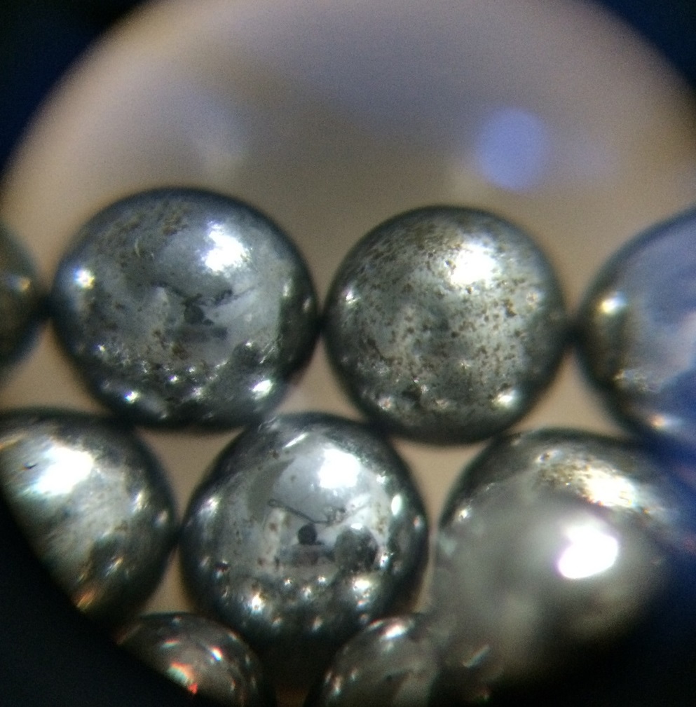
I have ordered Grade 10 balls from eBay for my ballscrew and this is what they send me.
Please Log in or Create an account to join the conversation.
- PCW
-

- Offline
- Moderator
-
Less
More
- Posts: 17961
- Thank you received: 5265
21 Nov 2017 13:41 #102133
by PCW
Replied by PCW on topic Retrofitting a 1986 Maho MH400E
Those look like slingshot grade balls...
Please Log in or Create an account to join the conversation.
Moderators: piasdom
Time to create page: 0.357 seconds