Retrofitting a 1986 Maho MH400E
- Glemigobles
- Offline
- Elite Member
-

- Posts: 201
- Thank you received: 18
Now I have a question to Mark regarding the EXE. Please excuse my being a total electronics noob. In your files you connect 12V to the Heidenhain board, with a red cable. In my wiring diagram for the MAHO, there is no power fed through any of the pins to the EXE board (at least from what I can tell), and the red cables terminate in the CNC controller with "Marker", which I have no idea what it means in the world of German electronics, but it has no voltage.
It looks to me as though 19A4 doesn't get any power from anywhere, and you also write in the beginning of your Word document that the card doesn't get power from the Phlips back plane. So what should I do?
Also, I made one change to your retrofit plan by not removing the pendant and control panel. I'd like to connect them to the 7i73. I just don't have the time to make my own stuff now, but I might end up controlling the mill using a keyboard before I manage to figure out all the connections and interface them with LCNC. Due to this change, I bought an additional 24V PSU for the Mesa boards, since I'm not removing the pendant power connections.
I've been working on this retrofit fulltime for a week now. The most time consuming activities so far included: soldering a DB25M-DB25M cable (they didn't have it on hand when I placed my order; should've ordered it anyway considering how much time it took to make one); drilling and tapping holes in the old case plates for all the cards; splitting, marking and crimping the connections on ribbon cables 28X1 and 28X2. It looks like the drive wiring will be far less of a pain than the relay.
Currently, I'm working on connections to the 7i77. Once everything is wired, I'll start configuring this setup. I'll probably make a new PNCConf file to set up just the drives and then configure the relay board IO to the 7i84 manually. It's ironic how the 7i74 board was implemented to save time on splitting CAT5 cables but then you have to set up the connections by hand in hal instead of using the wizard.
BTW, how did you attach the 7i84 to the cabinet door? Double-sided tape, velcro strips? Or did you drill mounting holes? I was thinking of double-sided tape, since the board is screwed on to a piece of acrylic. I attached pretty much everything (including the Heidenhain EXE) with M3 risers, PC style, as that's pretty much all I know
") I have no plans to mount the ATX PSU to anything right now.
I have no plans to mount the ATX PSU to anything right now.In the attachments is a pic of my current set-up and the schematic for the EXE connections (blatt 26) from DMG.
Please Log in or Create an account to join the conversation.
- RotarySMP
-
 Topic Author
- Offline
- Platinum Member
-

- Posts: 1627
- Thank you received: 595
- Yes 24VDC is the field power in the MAHO, as you are switching 24VDC relays.I solved my problem by actually connecting the field power on the 7i77 and 7i84 to a 24V PSU, instead of the 5V one.
- The Heidenhain three axis EXE used in my Phillips had no single PSU. and no back plane connection to the Phillips rack. Actually, the only thing common about the three axis is that they are on one piece of fiberglass circuit board. The three are electrically separate. Have a look on the board. On mine there was test points for gnd, +5V and +12V. The 5V circuit is powered by the MESA. (Note the stand alone EXE 602 only needs this 5V). But until I supplied 12V to the appropriate pin of each EXE, they didn't work. I clipped one of the PC's PSU power cables for a hard drive, and use it as my 12V source, adding a terminal I called 500, with it's ground called 501, and tied with the MEA ground. On the cable from each EXE to the MESA, you need to terminate the red wire from this cable to your new 12V terminal. My original wiring diagram from MAHO was also wrong with EXE wiring. It was the only error I found in the schematics.Now I have a question to Mark regarding the EXE. Please excuse my being a total electronics noob. In your files you connect 12V to the Heidenhain board, with a red cable. In my wiring diagram for the MAHO, there is no power fed through any of the pins to the EXE board (at least from what I can tell), and the red cables terminate in the CNC controller with "Marker", which I have no idea what it means in the world of German electronics, but it has no voltage.
It looks to me as though 19A4 doesn't get any power from anywhere, and you also write in the beginning of your Word document that the card doesn't get power from the Philips back plane. So what should I do?
The MAHO control panel look like it is a simple multiplexed 8x10 matrix, with not all nodes used.. Here is the pinout. Check this carefully, as I never used it. Using LinuxCNC' matrix_kb comp should work. However, As I understand it, you can not use the text entry keys (numbers etc), as the user space is separate from the HAL command space (not sure of the terminology.Also, I made one change to your retrofit plan by not removing the pendant and control panel. I'd like to connect them to the 7i73. I just don't have the time to make my own stuff now, but I might end up controlling the mill using a keyboard before I manage to figure out all the connections and interface them with LCNC. Due to this change, I bought an additional 24V PSU for the Mesa boards, since I'm not removing the pendant power connections.
[attachment=19219]Phillip 432 keyboard pinout.gif[/attachment
Realistically, that Phillips keyboard is not that useful, as it is missing the G,M,F, S, O, X, Y, z, I, J, K, R, T buttons you need for ISO G code, at least if you want to use the MDI and canned cycles.
- Yes the drive interface is very simple, I used chopped up CAT 5E cable for good shielding.I've been working on this retrofit fulltime for a week now. The most time consuming activities so far included: soldering a DB25M-DB25M cable (they didn't have it on hand when I placed my order; should've ordered it anyway considering how much time it took to make one); drilling and tapping holes in the old case plates for all the cards; splitting, marking and crimping the connections on ribbon cables 28X1 and 28X2. It looks like the drive wiring will be far less of a pain than the relay.
-If you use the same pins I did, you should be able to cut paste those sections from my HALCurrently, I'm working on connections to the 7i77. Once everything is wired, I'll start configuring this setup. I'll probably make a new PNCConf file to set up just the drives and then configure the relay board IO to the 7i84 manually. It's ironic how the 7i74 board was implemented to save time on splitting CAT5 cables but then you have to set up the connections by hand in hal instead of using the wizard.
- Drilled two holes through the door and mounted a short length of DIN Rail. since I goo the din mounting kits form MESA: Otherwise I'd drill and use stand offs. DOuble sided tape will fall off sooner or later..BTW, how did you attach the 7i84 to the cabinet door? Double-sided tape, velcro strips? Or did you drill mounting holes? I was thinking of double-sided tape, since the board is screwed on to a piece of acrylic.
- I use a little Micro-ITX PSU, and DIN rail mounted it as well.I attached pretty much everything (including the Heidenhain EXE) with M3 risers, PC style, as that's pretty much all I know
Please Log in or Create an account to join the conversation.
- RotarySMP
-
Topic Author
- Offline
- Platinum Member
-
- Posts: 1627
- Thank you received: 595

This matrix keyboard didn't come out last time.
Attachments:
Please Log in or Create an account to join the conversation.
- Glemigobles
- Offline
- Elite Member
-
- Posts: 201
- Thank you received: 18
Regarding the EXE, mine also had separate circuits for each axis. I'd never spot a fault in the schematics!
Originally, the Philips control displayed all the letters on the screen and you'd choose the one you wanted for your code. Then, the control progressively limited your input based on previous choices (e.g. if you started a pocket cycle, the control would require you to enter all the relevant parameters and the other letters would disappear; I thought it was an elegant, if somewhat cumbersome solution to not having a fully-featured keyboard). One of the best things about this retrofit is that once it gets going, I can shamelessly copy programs directly from my workshop PC with Fusion 360, so there'd be very little manual programming (for a few months at least, probably). I guess it's also possible to use a keyboard in addition to the panel, or are they mutuall exclusive? If so, I have to set up Linux to automatically log in and start LinuxCNC, which I haven't done yet.
The plates from the Philips case limit the footprint of the new parts in comparison to DIN rail mounting due to the vertical orientation, but they're not really all that stable. Without the support of the entire frame of the case, the individual plates are kind of wobbly.
Please Log in or Create an account to join the conversation.
- RotarySMP
-
Topic Author
- Offline
- Platinum Member
-
- Posts: 1627
- Thank you received: 595
Yu are right that the phillips keyboard and a normal keyboard are not mutually exclusive. I use on of the little logitech blue tooth keyboards with a build in mousepad when I need more than just the onscreen touch keyboard. Works very well. WHen setting up matrix-kb, you have to be careful to copy the "_" verse "-" in the HAL. There is one place where it has to be an underscore, but then that turns into dashes in the pins (or was it vice versa).
Yesterday I took a shot at machining out the internal space of the pendant housing. Was too aggressive with both the Ap and Ae, and the mill took the ferry over the Jordan. 14mm HSS 2 flute. 61m/min, 0.054mm/tooth, and Ae =10 mm deep.
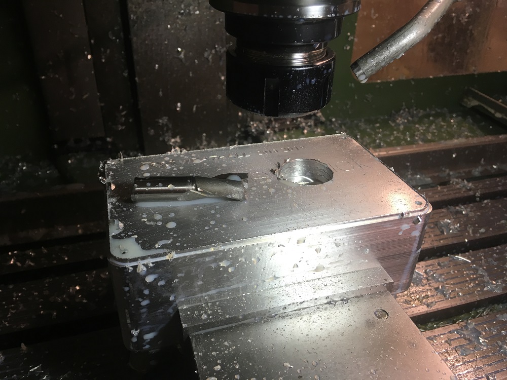
The next attempt is with a 16mm two flute, and since I need to go 51mm deep, I have dialed way back to 3mm per level.
Mark
Attachments:
Please Log in or Create an account to join the conversation.
- Glemigobles
- Offline
- Elite Member
-
- Posts: 201
- Thank you received: 18
So on the MAHO I'd use S=1500 and F=120 with an 8mm depth of cut (Ap) for your 16mm two flute. Keep using flood coolant to get the chips out and prevent the aluminum from clogging up your endmill. Your previous endmill broke I think because you used an excessive depth of cut with an fz that was too high. Without knowing the endmill manufacturer's recommendations it's risky to assume an Ap>1/2D.
Please Log in or Create an account to join the conversation.
- RotarySMP
-
Topic Author
- Offline
- Platinum Member
-
- Posts: 1627
- Thank you received: 595
I did one layer yesterday at Ap=3mm, Vc=1150 RPM and Fz= 170mm/min, and had a fair bit of chatter. I was already planning to search for better recommended feeds and speeds , so I just recalculated the tool path with the Ap=8, Vc=1500 and Fz=120 you recommended. I'll report back once I test it this afternoon. At the same time I'll download the HAL/INI and post it.
Mark
Please Log in or Create an account to join the conversation.
- HiioHoi
- Offline
- New Member
-

- Posts: 4
- Thank you received: 4
Here is example code:
G91 G81 X0 Y0 Z-11. R5. F100
X4. L20 (Good value for side step is about 20-25% of cutters D)
G80
G90
Good example from NycCnc:
Please Log in or Create an account to join the conversation.
- RotarySMP
-
Topic Author
- Offline
- Platinum Member
-
- Posts: 1627
- Thank you received: 595
I dont have many tool holders, so I currently down use the tool changer comp. I just break my ngc files into separate tool files, and manually change tools and touch off.
Currently everything is in these three files.
Warning, my Y axis EXE channel died, and the Ebay special 601 EXE I bought is only 0.005mm resolution, so it is only 200 per unit scale. If your three exe's work, this need to be 1000.
Mark
Please Log in or Create an account to join the conversation.
- Glemigobles
- Offline
- Elite Member
-
- Posts: 201
- Thank you received: 18
Please Log in or Create an account to join the conversation.