- Configuring LinuxCNC
- Configuration Tools
- StepConf Wizard
- Forward Step / Backward Step - Vexta Question
Forward Step / Backward Step - Vexta Question
- andypugh
-

- Offline
- Moderator
-

- Posts: 19863
- Thank you received: 4636
CNC systems are complicated. One of the most complicated overall systems that there are.I feel bad because I am not used to needing help from other people this much
I am not sure what options you chose. If you selected a parallel port pin to be e-stop then I think it did the right thing.So, letting Stepconf set up the e-stop pin was not going to be enough....
Yes, that is correct.This creates signal called "net estop-ext " which reads hardware parallel port 13, correct?
net estop-ext <= parport.0.pin-13-in
You can invert the sense of the P-Port pin (in stepconf or by editing the HAL) to get this behaviour.I thought that the Linuxcnc wanted wants a FALSE state to proceed, meaning that a NC Estop switch hadn't been tripped.
net estop-ext parport.0.pin-13-in-notYes.Does this create a signal called "estop-out" which pretty much gets its input from the GUI button in axis? (via LinuxCNC's subsystem)
net estop-out <= iocontrol.0.user-enable-out
That is certainly possible. I have a machine where the on-screen button is entirely under hardware control. (which isn't actually what I intendedIf so, then that line not going to help me. I just want my hardware button to toggle the screen button. I want to shut off the estop event so I can enable the screen Power button, so I can turn my machine on.
") . I think that involves the pin you mention later, iocontrol.0.user-request-enable.
. I think that involves the pin you mention later, iocontrol.0.user-request-enable.Every HAL pin is polled every mS.The next problem I am having is: I don't know if LinuxCNC is going to watch a HAL pin, or if I have figure out how to create an event.
Well, that isn't entirely true, HAL pins are actually shared-memory locations and each HAL module reads its inputs and updates the outputs every time the thread it is in runs (and the modules run in the sequence of the "addf" commands in the HAL file)
Yes. I think that stepconf just creates the estop-out signal in case you want to use it in a different HAL file. As far as I can see it isn't used in your HAL?Wouldn't this be enough on it's own? As it's connecting the "estop-ext" signal to Estop watcher.
net estop-ext => iocontrol.0.emc-enable-in
It might be worth fiddling with the pins in a simulator to see what happens.To read the documentaiton also looks like this is involved somehow, but no one has brought it into play.
iocontrol.0.user−request−enable
If you open an axis sim config, then open Machine -> show HAL configuration you can set up a "watch" in the "watch" tab of the various HAL pins, and you can change their values in the command line at the bottom of the other tab.
However I prefer to issue the commands from a terminal window, because then you can have tab-completion.
halcmd -kfunlinkp iocontrol.0.emc-enable-in
setp iocontrol.0.emc-enable-in 1
setp iocontrol.0.user-request-enable 0
setp iocontrol.0.user-request-enable 1It seems to work for simulator systems with no hardware. Presumably it's due to the order of execution.I don't understand why I would want to create signal loopback with nothing in between to control it, start it, or stop it. This would seem to lock the system into a state, but I how could I chose which?
I think you are very close.Sigh. I am not very confident my machine will be running soon : (
You could comment-out the current e-stop lines (for the moment) and put in the loop
net estop-loop iocontrol.0.user-enable-out iocontrol.0.emc-enable-in
for testing.
Then you should be able to release e-stop and turn on the machine.
Please Log in or Create an account to join the conversation.
- BrendaEM
- Offline
- Elite Member
-

- Posts: 266
- Thank you received: 120
Thank you Andypugh, that got the F1/F2 working as advertised. : )
So far, I can enable the GUI and moves things around on the screen.
Though, the machine still doesn't move. I tried setting the step parameters, slowing them down to quite far at 50,000ns and 500,000ns just to be sure.
(I also set up the machine limits, which seem okay, though I still have to decide about homing points, but that seems like I will be able to do that.)
I checked the Halscope, and the xup and xdown signals pulses are being created by the system, but I am unsure if they are going out to the parallel port.
I've been heavily commenting the HALs that I've been uploading, so that they might help someone else.
Thanks you again.
Please Log in or Create an account to join the conversation.
- andypugh
-
- Offline
- Moderator
-
- Posts: 19863
- Thank you received: 4636
Are the motors free or locked?
Please Log in or Create an account to join the conversation.
- BrendaEM
- Offline
- Elite Member
-
- Posts: 266
- Thank you received: 120
The disabling is not wired in. I usually run these drivers this way, and they have a separate holding current, which can be set fairly low, so they don't get to warm from holding.
The motors are indeed holding.
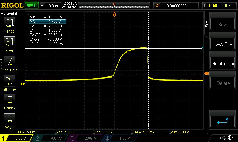
I might have found an issue. I hooked up the old Rigol 1054z, and I did see pulses coming from the parallel card.
The voltages look okay, not great but okay (I cursored them backwards in the pic, so the voltage is calculated backwards as well.)
The pulse is pretty rounded, but I don't think that's the problem.
However the pulse looks pretty short, not what I asked for.
I am going to try to make the high portion higher, and check a few more pins.
setp stepgen.0.steplen 50000 # High Portion of Step
setp stepgen.0.stepspace 500000 # Low Portion of Step
setp stepgen.0.dirdelay 500000 # Space Between Direction Change
Please Log in or Create an account to join the conversation.
- andypugh
-
- Offline
- Moderator
-
- Posts: 19863
- Thank you received: 4636
# X-Axis --------------------------------
setp stepgen.0.position-scale [AXIS_0]SCALE
setp stepgen.0.steplen 1
setp stepgen.0.stepspace 1

# X-Axis Step Timing
# Ref: http://linuxcnc.org/docs/html/man/man9/stepgen.9.html#TIMING
setp stepgen.0.steplen 50000    # High Portion of Step
setp stepgen.0.stepspace 500000 # Low Portion of Step
setp stepgen.0.dirdelay 500000  # Space Between Direction Change
Which is a bit odd, but ought to work (the second "setp" for each parameter should over-write the first).
Out of interest, how does your base-period (in the INI) compare to the step length you are seeing there?
If I am reading things right that is a 22uS step, which is probably the shortest step that can be made with your base period.
I think the question is why the rise-time is so slow. Do your drives have an option to use sinking inputs? Most parports have rather more drive capacity sinking current than sourcing it.
Please Log in or Create an account to join the conversation.
- BrendaEM
- Offline
- Elite Member
-
- Posts: 266
- Thank you received: 120
Yes, the rise is may be out of driver spec. I thought my board had schmitt triggers on it. I'd guess not on outputs. The supplied parallel cable is only 3 feet long. The scope reading was made directly to the terminals. That rise time in itself could be trouble.
About the driver inputs....
So these were custom drivers made by Vexta. I've been playing with them for a year or so, for various things. I've tested several drivers and motors. I've not been able to get them to sleep, but they otherwise run very reliably. All the motors, drivers, and axis work fine, driven from an Arduino, one at a time, during the construction of my machine.
I've been driving them from an Arduino. (which has really nice square wave edges, up until the point when the processor just can't switch the ports any faster. Without a terminating resistor, there's a little ringing, but the edges look otherwise nice.)
I had been been really running them non-inverted and varying the high side of the pulse length, thereby inverting them.
I've been doing some experimentation in LinuxCNC.
I just got done doing a test, inverting the parallel port signals and shortening the times, but it still doesn't work.
Looking at the scope, the high is inverted as I changed it to be, but pulse was only 1.45v high inverted.
I am going to clean up those duplicates and do one more test. Then I need a break.
Thanks for all the help.
Please Log in or Create an account to join the conversation.
- andypugh
-
- Offline
- Moderator
-
- Posts: 19863
- Thank you received: 4636
Some of those interface boards for the parallel port need a power supply. Some (apparently) need two. I assume that it has those?
If the drives have opto-isolated inputs, and you can get to both sides, then I would suggest a 5V supply pulled-down through the opto by the parport driving the drive directly. (bypass the interface board).
It seems like the problem here might be the parallel port or the interface board. (I think that we have concluded that LinuxCNC is making steps? The step length can only be integer multiples of the base period. (Actually, there is a way to get shorter steps, but it doesn't gain you much really).
Please Log in or Create an account to join the conversation.
- BrendaEM
- Offline
- Elite Member
-
- Posts: 266
- Thank you received: 120
I think that the steps are small enough.
Please Log in or Create an account to join the conversation.
- BrendaEM
- Offline
- Elite Member
-
- Posts: 266
- Thank you received: 120
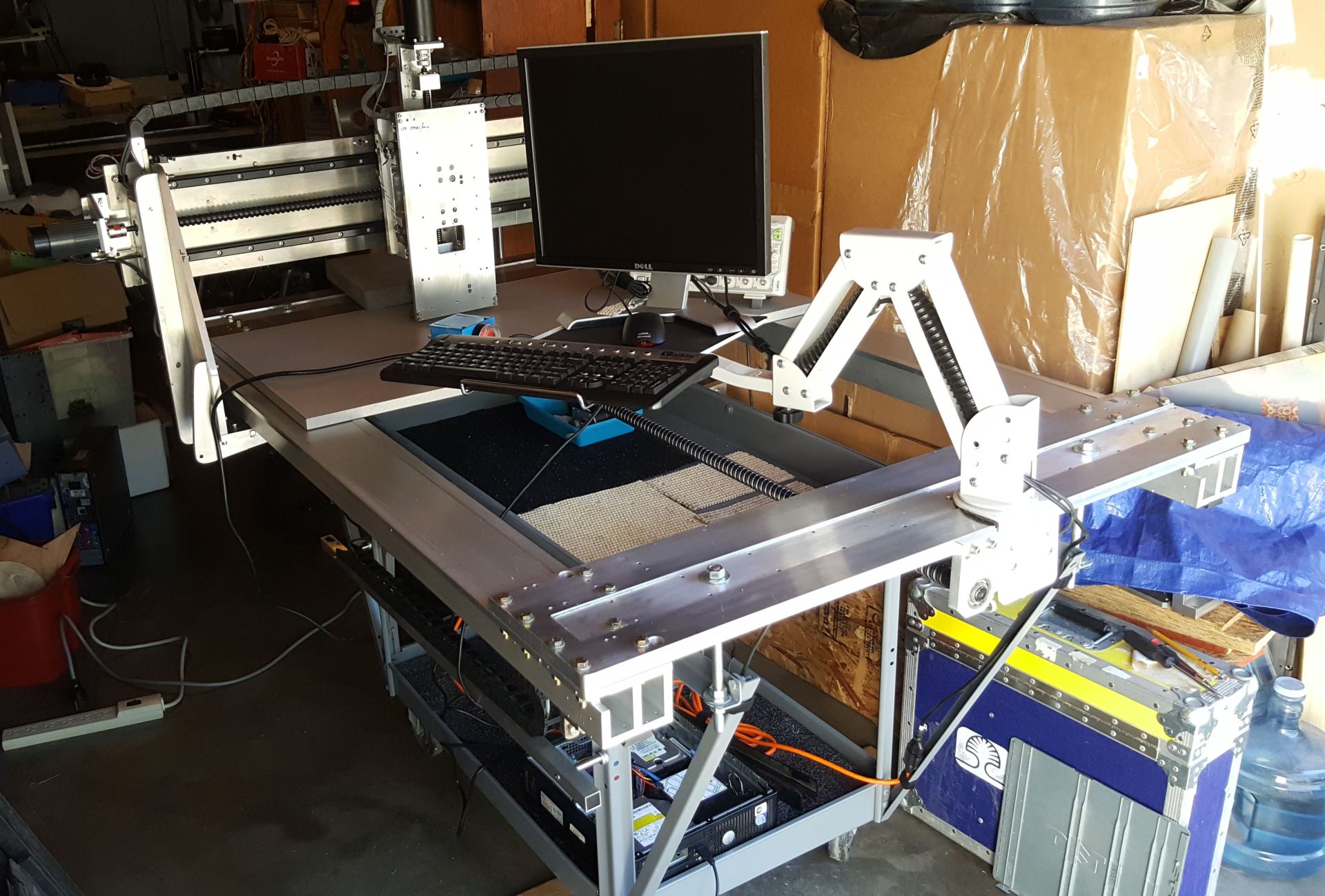
The aluminum plate the monitor arm is on, as well as the x-axis horizontal plate are 20mm thick. The ballscrews and rails are THK; the things that some companies throw in the scrap heap : O
Most of the gantry plates were cut out with an electric sabre saw. I had to grind them, and file the inside corners square. The long rails have the linear rails underneath to keep dust and chips out of them. I've drilled over 100 holes, and tapped more than 50 to put this thing together.
The envelope will be about 900mm x 1100mm x 120mm.
Aside from the interfacing, I have to pick out a spindle motor, get a longer monitor cable, get something for a table....
Please Log in or Create an account to join the conversation.
- BrendaEM
- Offline
- Elite Member
-
- Posts: 266
- Thank you received: 120
: )
It was a voltage problem with the Optocoupler board. I can't exactly double-post, so:
forum.linuxcnc.org/27-driver-boards/3443...lator-board?start=10
Thank you in no particular order: Andypugh, Tommylight, Grotius, Ozzyrob, Todd Zuercher, PCW, and Rodw, others, and for LinuxCNC.
I lowered the Y- acceleration really low to around 100 so the whole cart wouldn't roll when the y-axis moves, for now, and the thing runs smooth as silk. It was really cool to finally move two axis at once, three even!
I have to make a block setup to put under the cart so it won't roll.
I still have a myriad of adjustments to make.
Thanks again.
I guess I have to learn how to run this thing.
Please Log in or Create an account to join the conversation.
- Configuring LinuxCNC
- Configuration Tools
- StepConf Wizard
- Forward Step / Backward Step - Vexta Question