First Look: Cheap Parallel Port Opto Isolator Board
- ozzyrob
-

- Visitor
-

10 May 2018 00:39 #110478
by ozzyrob
Replied by ozzyrob on topic First Look: Cheap Parallel Port Opto Isolator Board
Being a lazy so & so ATM how much of delay would one get by using an opto-isolator to activate a second one (as in a lot of stepper motor drivers). Obviously there are opto-isolators and there are opto-isolators. I know this question has a lot of "depends" but there are some pretty slow opto-isolators out there, which maybe ok for input\output.
Just a thought I've had for bit.
Just a thought I've had for bit.
Please Log in or Create an account to join the conversation.
- BrendaEM
- Offline
- Elite Member
-

Less
More
- Posts: 266
- Thank you received: 120
10 May 2018 04:36 #110488
by BrendaEM
Replied by BrendaEM on topic First Look: Cheap Parallel Port Opto Isolator Board
Fifteen is a fair amount of CNC machines : )
Please Log in or Create an account to join the conversation.
- BrendaEM
- Offline
- Elite Member
-
Less
More
- Posts: 266
- Thank you received: 120
10 May 2018 04:46 - 10 May 2018 04:48 #110491
by BrendaEM
Replied by BrendaEM on topic First Look: Cheap Parallel Port Opto Isolator Board
I think I finished the wiring on the interface board. I didn't know what size cable I was going to use, so I didn't put a design in the housing.
I had an old USB able from an old webcam I was going to use to power the interface. It was resistive, losing about a volt over the length of a meter/yard. My roommate and I both considered that the cellphone switching power supply I tested it with might not put out 5 volts until there was a load on it, but the USB cable was indeed resistive.
Shaking my head, I held the end of an almost new USB extension cable in a pair of cutting pliers. Chop! I tinned the leads, drilled a hole in the housing, and worked for 15 minutes to cram a Harbor Freight crappy grommet in the housing. I put a zip tie on either end to use as a strain-relief. The new cable puts out 5 full volts.
After that, I eventually got the computer going. There is a surface mount power LED on the interface board.
I was able to test the limit switches. I have just a loop of wire right now for a hardware to software estop signal, but my machine has a hardware relay estop. I still want to get the hardware to software one going.
Anyway I have an HAL estop signal of FALSE, but I can't take LinuxCNC/Axis GUI off of Emergancy Stop to turn it On.
I posted a thread here:
forum.linuxcnc.org/24-hal-components/345...s-power-in-linux-cnc
Anyway, the inputs seem to be working, so I am making progress : )
Last edit: 10 May 2018 04:48 by BrendaEM.
Please Log in or Create an account to join the conversation.
- BrendaEM
- Offline
- Elite Member
-
Less
More
- Posts: 266
- Thank you received: 120
11 May 2018 01:36 - 11 May 2018 01:37 #110556
by BrendaEM
Replied by BrendaEM on topic First Look: Cheap Parallel Port Opto Isolator Board
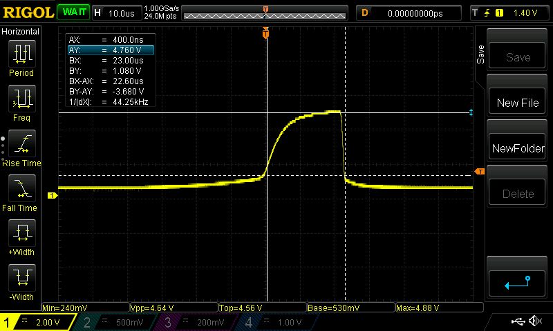
If this is the best I can get from the board. I'm considering it a do not buy.
I may try another power source, perhaps another cable, but I thought this thing had shmidt triggers in it.
I may try another power source, perhaps another cable, but I thought this thing had shmidt triggers in it.
Last edit: 11 May 2018 01:37 by BrendaEM.
Please Log in or Create an account to join the conversation.
- ozzyrob
-
- Visitor
-
11 May 2018 02:23 #110559
by ozzyrob
Replied by ozzyrob on topic First Look: Cheap Parallel Port Opto Isolator Board
Just out of interest what is the part number of the optos ?
Please Log in or Create an account to join the conversation.
- BrendaEM
- Offline
- Elite Member
-
Less
More
- Posts: 266
- Thank you received: 120
11 May 2018 03:42 - 11 May 2018 03:46 #110565
by BrendaEM
Replied by BrendaEM on topic First Look: Cheap Parallel Port Opto Isolator Board
There is C519 printed on them. Not quite NECs. I had hoped that they would have worked. I don't know where else to get a board with this alleged functionality because I needed something very generic for my application.
Last edit: 11 May 2018 03:46 by BrendaEM.
Please Log in or Create an account to join the conversation.
- ozzyrob
-
- Visitor
-
11 May 2018 04:05 #110567
by ozzyrob
Replied by ozzyrob on topic First Look: Cheap Parallel Port Opto Isolator Board
A lot of the boards that are on the cheaper side tend to use a slower opto.
Roll you own with kicad and then get pcb's made. You might even be able a sell any extras.
I've used these guys in the past with excellent results about a 2 week turn around to Australia.
www.elecrow.com/
Some good info here on design:
www.anderswallin.net/2006/08/optoisolato...mesa-5i20-servocard/
Mesa also sell a card...might be a bit over kill for your needs.
store.mesanet.com/index.php?route=product/product&product_id=93
Please Log in or Create an account to join the conversation.
- BrendaEM
- Offline
- Elite Member
-
Less
More
- Posts: 266
- Thank you received: 120
12 May 2018 04:17 - 12 May 2018 04:47 #110592
by BrendaEM
Replied by BrendaEM on topic First Look: Cheap Parallel Port Opto Isolator Board
I am disappointed with the interface card at this point. The card is not doing what it's supposed to.
The instructions are have nice pictures, but the ChinEngrish does not read well.
Looking at the blurry output schematic, it looks like the voltage is pulled up with a resistor, and the opto-coupler pulls it down.
Aside from the rounded corners, I think what's going on is that the resistor pulling the output pins high is too high of a resistance to drive the driver optos. While it has 4+ volts swinging in the breeze, as soon the opto in the front end of the stepper driver sinks some 10 lousy MA, it pulls the voltage down to around 1.7 volts, that is not going to drive the optos in the stepper driver because they have a current limiting resistor, to work with 5 volts.
I suspect that by pulling the jumpers, the optos can be driven by a higher voltage, that might raise it's output, but I will have to drive it at 7 volts to get 5 out. As far as I can tell, the board's output is supposed to be isolate, or they wouldn't have included the jumpers to disconnect the power rails.
I never appreciated the Aduino's outputs until I ran into this thing.
I don't have the resources to come up with my own opto board, but if I did it would have replaceable optos, and good instructions.
I PM'ed some here about the board. I also sent a message to the ebay seller of the board. I figured the seller might want to get involved in this, send me better instructions, you know, to protect his rating : )
This was not the turn-key opto board solution I was looking for.
Last edit: 12 May 2018 04:47 by BrendaEM.
Please Log in or Create an account to join the conversation.
- BrendaEM
- Offline
- Elite Member
-
Less
More
- Posts: 266
- Thank you received: 120
12 May 2018 07:37 - 12 May 2018 07:50 #110593
by BrendaEM
Replied by BrendaEM on topic First Look: Cheap Parallel Port Opto Isolator Board
I got it working!!!
: )
Low voltage was the problem. I pulled the jumpers from the board, and at first I tried 9 volts. Checking the oscilloscope, the voltage output was over 2 volts. Half of the motor directions worked.
Then, I used a 12 volt power supply, putting a diode in line to cause a voltage drop, dropping to around 11 volts. Now, all the motors and directions work!
Thank you in no particular order: Andypugh, Tommylight, Grotius, Ozzyrob, PCW, Todd Zuercher, and Rodw, others, and for LinuxCNC.
I will shoot some video in the morning.
Last edit: 12 May 2018 07:50 by BrendaEM.
Please Log in or Create an account to join the conversation.
- Grotius
-

- Offline
- Platinum Member
-

Less
More
- Posts: 2419
- Thank you received: 2348
12 May 2018 15:26 #110605
by Grotius
Replied by Grotius on topic First Look: Cheap Parallel Port Opto Isolator Board
@Hi Brenda,
Nice to hear your machine is working !!
The best is to use the - step as signal from motor driver to your brake out board. Some motor drives will not work with + step signals.
Nice to hear your machine is working !!
The best is to use the - step as signal from motor driver to your brake out board. Some motor drives will not work with + step signals.
Please Log in or Create an account to join the conversation.
Moderators: PCW, jmelson
Time to create page: 0.202 seconds