- Hardware & Machines
- Computers and Hardware
- Remora - Rpi Software Stepping Using External Microcontroller via SPI
Remora - Rpi Software Stepping Using External Microcontroller via SPI
- mhel
- Offline
- Senior Member
-

- Posts: 47
- Thank you received: 6
Please Log in or Create an account to join the conversation.
- cakeslob
- Offline
- Platinum Member
-

- Posts: 925
- Thank you received: 277
I compiled it using the online compiler , and the bin was 40.3kb, is this an acceptable way to do it or do I need to install mbed ide to have it compile for os5? I didnt see anything to selecting versions with online compiler. It sent a few deprecated function flags while compiling but thats it. Im sorry if this question was answered earlier on.
Second, is this being loaded from ST-LINK, DFU, or via SD card?
Thank you for your patience, and hard work.
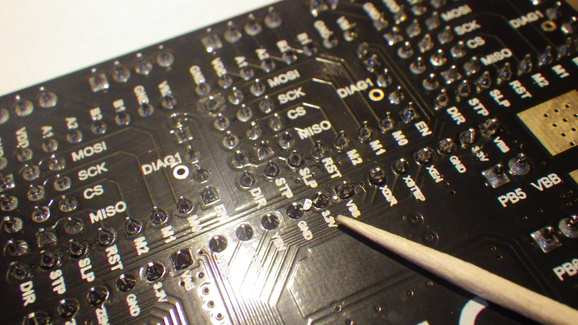
I will have to provide my own QC03 sticker after I clear all these stray solder balls from the board myself.
Attachments:
Please Log in or Create an account to join the conversation.
- mhel
- Offline
- Senior Member
-
- Posts: 47
- Thank you received: 6
But yes according to the schematic PC13 is what turns on the motor via the opto.
As your board uses a bootloader, you just copy the bin file to the SDcard and put
it on the board. I'm not sure about the DFU, but you can also use ST-Link but you
need to offset where it programs the flash somehow, otherwise it will overwrite your
bootloader (just found out about it
") ) . BTW, IDE is not necesarry but nice if it
) . BTW, IDE is not necesarry but nice if ithas debug facility. It really helps if you can see the registers too, Scott will fill you in with more info, he knows more.
Please Log in or Create an account to join the conversation.
- cakeslob
- Offline
- Platinum Member
-
- Posts: 925
- Thank you received: 277
The STM32F405xx and STM32F407xx are part of the STM32F4 family. They are fully pinto-pin, software and feature compatible with the STM32F2xx devices
The STM32F446xC/xV is software and feature compatible with the STM32F4 family.
The STM32F446xC/xV can be used as drop-in replacement of the other STM32F4 products
Does this mean STM32 family chips will have similar firmware and just need some pin revisions/custom target to work on other stm324xx boards?
Please Log in or Create an account to join the conversation.
- mhel
- Offline
- Senior Member
-
- Posts: 47
- Thank you received: 6
I think so. Look at the content of TARGET_SKRV2, then also look at mbed-os/targets/TARGET_STM/TARGET_STM32F4.
Does this mean STM32 family chips will have similar firmware and just need some pin revisions/custom target to work on other stm324xx boards?
Please Log in or Create an account to join the conversation.
- scotta
-

- Offline
- Platinum Member
-
- Posts: 958
- Thank you received: 487
I used Mbed studio and it actually worked with the ST-Link in debug mode as well. Didn't test when using the standard SD bootloader though.Ok, the rx and tx are on the same TFT connector as the 1.4 except flipped 180 degrees, PB_4 is going to HE1_pwm > HE1_MOSFET > D13, and PC_13 is going to MOT_POWER which turns on the VMOT (and VBB?)via the U5 opto and the Q1 mosfet correct? How does it provide feedback for the anti driver reverse to work? Something to do with Q2 mosfet? What a handy feature (lol sorry).
I compiled it using the online compiler , and the bin was 40.3kb, is this an acceptable way to do it or do I need to install mbed ide to have it compile for os5? I didnt see anything to selecting versions with online compiler. It sent a few deprecated function flags while compiling but thats it. Im sorry if this question was answered earlier on.
Second, is this being loaded from ST-LINK, DFU, or via SD card?
Thank you for your patience, and hard work.
I will have to provide my own QC03 sticker after I clear all these stray solder balls from the board myself.
When trying to get the blinky to work I had to figure out that enable circuit as well. I think it would be useful for drivers that we can talk to like the TMC2209's. No comms, don't enable the drivers. For a dumb driver I'll need to look at the circuit diagram / Marlin code to understand what checks they are doing before motor enable.
When we get the port going on the STM32 it will open up a heap of board options. We'll need to port to the STM32F1 series as well.
Please Log in or Create an account to join the conversation.
- Bari
-
 Topic Author
- Offline
- Platinum Member
-
- Posts: 639
- Thank you received: 234
AC Servo Driver for STM32F4
github.com/rene-dev/stmbl/wiki
Please Log in or Create an account to join the conversation.
- gtt38
- Offline
- Senior Member
-
- Posts: 79
- Thank you received: 4
Now i can fully help to port remora on the STM32, i m dowloading the repo right now...
Please Log in or Create an account to join the conversation.
- Bari
-
Topic Author
- Offline
- Platinum Member
-
- Posts: 639
- Thank you received: 234
There was someone that got it running about 10 years ago on an ARMv5 or v6 with a few hundred megs of RAM.
code.google.com/archive/p/miniemc2/downloads
Please Log in or Create an account to join the conversation.
- scotta
-
- Offline
- Platinum Member
-
- Posts: 958
- Thank you received: 487
I think I'm going to like the STM32 version of Remora when the port is complete. The SPI comms are now running x4 faster (25Mhz) than on the LPC1768. The SPI actually pre-loads the buffers so we don't need hit the E-stop button twice to get the comms loop back active.
I'm also proposing to alter the SPI checking logic as we can now use the Slave Select line, via EXTI interrupt, to trigger the DMA transfer and packet checking. This will increase the noise tolerance on the SPI even more.
One step closer...
Please Log in or Create an account to join the conversation.
- Hardware & Machines
- Computers and Hardware
- Remora - Rpi Software Stepping Using External Microcontroller via SPI