
- Posts: 33
- Thank you received: 6

Please Log in or Create an account to join the conversation.
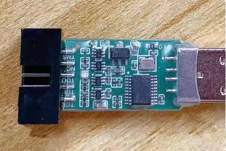
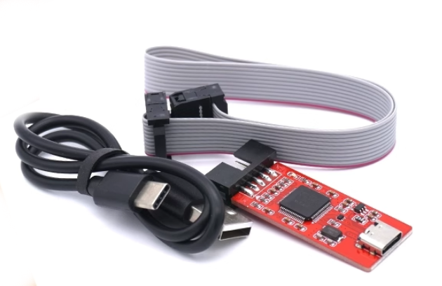
I wouldn't know for sure, Oliver. Nice thing about Gowin's is the endless jtag probes avail, for all I know. I have 3 here that works perfectly fine (up to 10~15mhz). The one you saw in previous visuals (FT232 based), and the ones below. All <$15.Do you think it could also work with a USB blaster?
Please Log in or Create an account to join the conversation.
Please Log in or Create an account to join the conversation.
Please Log in or Create an account to join the conversation.
fixed in the dev branchOnly source code I've had to change was for the board family to be recognized as a its high-speed C7/i6 type.
/riocore/riocore/boards/MecanixDev/board.json
[-] "family": "GW1N-9C",
[+] "family": "GW1N-9C7",
/riocore/riocore/generator/toolchains/gowin/toolchain.py
Line 103:
[+] if family == "GW1N-9C7":
[+] prj_data.append(f' <Device name="{family_gowin}" pn="{ftype}">gw1nr9c-017</Device>')
That was the reason my PIN03, PIN13, PIN 15 (high speed bank) was not working. The Gowin was always compiling for a C6/I5 fpga type
But allpins works now!!
Please Log in or Create an account to join the conversation.
Before sending this out to the pcb fab, and out of fear this would have been too good to be true, I've set my function generator to 'noise' and beaten up an input with the oscope trigger set to catch a low level. It did after a few seconds. Be pleased to know your advice was taken, I've added 20K pupps on the inputsimage missing /media/kunena/emoticons/cool.pngI'm going to have to disagree with you on the need for pull up or pull down resistors on inputs, especially with switches (unless the switch is switching to either zero or 5v)and rotary encoder that have an open collector output. Without a pullup or pull down resistor the input is going to float, until that input has a definite logic level on it. With high impedance inputs it requires very very little current to switch the input, if the voltage is at the right level. Generally on a chip such as the venerable 74xx245 when the enable inputs are in the disable state the output is considered to be in a "high impedance state" and is unable to "drive" the outputs.
Honestly any input that is connected via a cable needs a pullup or pulldown resistor for the case of a breakage in the signal wire, especially with an MPG, if teh signal wire breaks you want that input at the board end to held at a known level. The last thing you want is for your input to pick up stray noise and start oscillating. The chip wont "know" if it is a legitimate signal or noise and will pass that on to the other side.
That's why sometimes I feel am opto isolator is a bit better in this respect as the current required to drive the LED in normal situations is a little higher than induced noise in the line.
Never in my life have I designed a digital circuit that takes external off board signals with pullup or pulldown resistors, or inputs that get the input from a SPST switch from an on board switch without a pullup or pull down.
Please Log in or Create an account to join the conversation.

