
- Posts: 12169
- Thank you received: 4153

Yeh, that is due to a bigger stuff up. The enclosure is 400 x 400. I removed the backing plate and I carefully marked out all mounting bolts and inserted nutserts everywhere to mount everything. Then mounted everything only to find the backing plate was not square like the enclosure! So the plate is rotated 90 degrees from where I planned.Rod, drives should be mounted vertically, as noted in their manuals.
Please Log in or Create an account to join the conversation.
I would do this a but differently
Let the mains power come in and use some DIN rail terminals from Ocean controls. They have some Bus bar connectors to join a few together so that are all common. you'll need some green earth terminals as well
Grab something like this industrial power point but seperate the two pieces and flush mount to your enclosuere
www.tropac.com.au/10-AMP-250V-3-Flat-Pin-Switched-Socket
Use the switch as your main power switch and the power point for your router. Put a household breaker on a Din rail for circuit protection
So now you need to switch your router from your 7i96s.
You could use a Jaycar SSR (you also need the heat sink on this page)
www.jaycar.com.au/solid-state-relay-4-32...a-switching/p/SY4084
Or you could use a contractor from tropac but make sure it will switch with 24v DC (some are AC), you may end up with a 3 phase one
www.tropac.com.au/search?keywords=contactor
Between your mains power and the 7i96s, use an EMI filter www.jaycar.com.au/240v-ac-emi-filter/p/MS4001 . Then run the mains power to your 5v and 24v power and 36 volt power.
For your estop, Jaycar's one has 1 x NO and 1 x NC contactor. set it up so that the NO side switches 24v to an input and the NC side is on the mains power to your stepper motor supply and your router power point. The goal is that hitting estop will turn the router off and disable motion. We also want to send a signal back to the 7i96s so it knows estop has been pressed. the 7i96s will be powered on all the time.
Hope you have followed thaf!
Please Log in or Create an account to join the conversation.
Please Log in or Create an account to join the conversation.
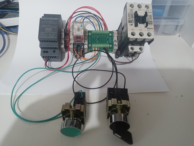
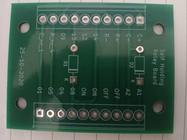
Here's an explanation of "Latching Relays", which is what my schematic shows. I made up some PCBs to make the connections easier.
www.pcbway.com/blog/PCB_Basic_Informatio...Relays_d665ce9b.html
Please Log in or Create an account to join the conversation.
Please Log in or Create an account to join the conversation.
Seems a bit excessive and not very useful.
It is much better to use a single small industrial switch and 4 of automatic fuses inside the control box, you can switch on/off automatic fuses as they can handle a bit of torture although they are not made for it, but since they will be used during testing only, they will be fine.
Please Log in or Create an account to join the conversation.
