Kinematics... again:/
- andypugh
-

- Offline
- Moderator
-

Less
More
- Posts: 19863
- Thank you received: 4636
11 May 2017 12:38 #93019
by andypugh
Replied by andypugh on topic Kinematics... again:/
In LinuxCNC v2.8 there are separate sections in the INI for [JOINT_0] and [AXIS_X] for example.
For a non-trivkins robot I strongly suggest using LinuxCNC v2.8, actually.
What errors did you get? You can copy from the error dialog and paste here.
For a non-trivkins robot I strongly suggest using LinuxCNC v2.8, actually.
What errors did you get? You can copy from the error dialog and paste here.
The following user(s) said Thank You: Boogie
Please Log in or Create an account to join the conversation.
- bkt
-

- Offline
- Platinum Member
-

Less
More
- Posts: 1111
- Thank you received: 114
11 May 2017 15:46 - 11 May 2017 15:49 #93029
by bkt
Replied by bkt on topic Kinematics... again:/
your robot is on video at first your post?
in these case you need to change your kins. You not can use the robokins .... but you can modify it .... actually (probabily because not read it) axis0 or axis1 not perform the linear movement that see on video ... robokins has 6 rotary axis ... you must add your optional linear axis in these way:
if you not use joint 5 or 4 not connect it at all but insert it on hal and ini file ... simply make it unconnected and perform zero axis on place ....
You have an optional join/axiswhich works in addition to some axis in cartesian world so probabily you must add & subtract it in linear manner (so in these case joint = axis) from x or y or z ... never try to play with robokins so I not know the cartesian axis orientation ... but these is your first kins problem.
regards
Giorgio
in these case you need to change your kins. You not can use the robokins .... but you can modify it .... actually (probabily because not read it) axis0 or axis1 not perform the linear movement that see on video ... robokins has 6 rotary axis ... you must add your optional linear axis in these way:
world->d = joint[6]; and world->d = joint[6];You have an optional join/axiswhich works in addition to some axis in cartesian world so probabily you must add & subtract it in linear manner (so in these case joint = axis) from x or y or z ... never try to play with robokins so I not know the cartesian axis orientation ... but these is your first kins problem.
regards
Giorgio
Last edit: 11 May 2017 15:49 by bkt.
The following user(s) said Thank You: Boogie
Please Log in or Create an account to join the conversation.
- andypugh
-
- Offline
- Moderator
-
Less
More
- Posts: 19863
- Thank you received: 4636
12 May 2017 14:37 #93092
by andypugh
I believe that the robokins that I posted was the kinematics used with the actual machine in the video.
Replied by andypugh on topic Kinematics... again:/
your robot is on video at first your post?
in these case you need to change your kins. You not can use the robokins o
I believe that the robokins that I posted was the kinematics used with the actual machine in the video.
Please Log in or Create an account to join the conversation.
- Boogie
- Offline
- Premium Member
-

Less
More
- Posts: 97
- Thank you received: 9
12 May 2017 15:06 #93098
by Boogie
Replied by Boogie on topic Kinematics... again:/
I was given another PC to play with and i'm going to install linuxcnc 2.8 as Andy suggested. It will take some time though. I'm curious about those joints. The joints count used in INI/HAL have to be the same as in kinematics file, right? According to C file (robokins.c) first joint (joint 0) is linear so i thought i have to set it linear in INI file as well.
Mr. K-1: the sentence:
world->d = joint[6]; and world->d = joint[6];
is a mystery for me, firstly b'cause both parts are the same, secondly i thought there are XYZ ABC and UVW coords in cnc world...
Mr. K-1: the sentence:
world->d = joint[6]; and world->d = joint[6];
is a mystery for me, firstly b'cause both parts are the same, secondly i thought there are XYZ ABC and UVW coords in cnc world...
Please Log in or Create an account to join the conversation.
- Boogie
- Offline
- Premium Member
-
Less
More
- Posts: 97
- Thank you received: 9
12 May 2017 19:00 #93106
by Boogie
Replied by Boogie on topic Kinematics... again:/
Ok, but where is LinuxCNC v.2.8? On linuxcnc.org the highest number is 2.7.8
Here is info on 2.7.8 version but no LiveCD ISO source:
linuxcnc.org/2016/11/09/LinuxCNC-2.7.8/
LiveCD ISO source is for 2.7 Wheezy:
linuxcnc.org/docs/2.7/html/getting-start...etting-linuxcnc.html
Here is info on 2.7.8 version but no LiveCD ISO source:
linuxcnc.org/2016/11/09/LinuxCNC-2.7.8/
LiveCD ISO source is for 2.7 Wheezy:
linuxcnc.org/docs/2.7/html/getting-start...etting-linuxcnc.html
Please Log in or Create an account to join the conversation.
- Todd Zuercher
-

- Offline
- Platinum Member
-
Less
More
- Posts: 4745
- Thank you received: 1454
12 May 2017 19:26 #93108
by Todd Zuercher
Replied by Todd Zuercher on topic Kinematics... again:/
2.8 is currently the development branch of Linuxcnc (aka Master). You can get it from buildbot by adding the appropriate repository references found here.
buildbot.linuxcnc.org/
buildbot.linuxcnc.org/
The following user(s) said Thank You: Boogie
Please Log in or Create an account to join the conversation.
- bkt
-
- Offline
- Platinum Member
-
Less
More
- Posts: 1111
- Thank you received: 114
13 May 2017 10:09 - 13 May 2017 10:13 #93129
by bkt
Replied by bkt on topic Kinematics... again:/
@Boogie Sorry But I see robokins.c file ... not the same as robot that I see on video ....
this ...is a simplistic way of communicating that you need to add a linear axis to the kinematic .... The correct letters to use are those listed by Boogie ... in that case you have to review the other ones as well.
I did not realize that you had your already pretty ready kinematics.
In this case the problem is just connecting the kinematic to Hal file?
Did I explain the mystery? My English I know I'm terrible ... but I'm able to build different kind of machines .... so sometimes I let myself go in .... for me it is study.
After these ... You can share your kins?
In the past I use correctly delta robot and scara kins with Lcnc 2.5 (not ja) ... JA is more flexible and It has more features for robots and unusual kins .... It is highly recommended to use it ... indeed it is necessary ... but it does not solve all the problems for connect cutomkins to Lcnc hal file.
I try to be clearer .... if you have problems connecting between customkins and hal files .... changing versions those remain. ... I would say that the greatest advantage is the separation between joints and axes. That said, you should still be able to connect customkins to hal files.
Regards
Giorgio
this ...
world->d = joint[6]; and world->d = joint[6];I did not realize that you had your already pretty ready kinematics.
In this case the problem is just connecting the kinematic to Hal file?
Did I explain the mystery? My English I know I'm terrible ... but I'm able to build different kind of machines .... so sometimes I let myself go in .... for me it is study.
After these ... You can share your kins?
In the past I use correctly delta robot and scara kins with Lcnc 2.5 (not ja) ... JA is more flexible and It has more features for robots and unusual kins .... It is highly recommended to use it ... indeed it is necessary ... but it does not solve all the problems for connect cutomkins to Lcnc hal file.
I try to be clearer .... if you have problems connecting between customkins and hal files .... changing versions those remain. ... I would say that the greatest advantage is the separation between joints and axes. That said, you should still be able to connect customkins to hal files.
Regards
Giorgio
Last edit: 13 May 2017 10:13 by bkt.
Please Log in or Create an account to join the conversation.
- andypugh
-
- Offline
- Moderator
-
Less
More
- Posts: 19863
- Thank you received: 4636
13 May 2017 10:40 #93132
by andypugh
Replied by andypugh on topic Kinematics... again:/
The kins already has a linear joint, joint_0.
The x-position is made up of the linear joint[0] modified by the angle of the welding head, a4 according to the length of the end-effector, D3.
robokins.c is the actual kinematics from the video. I helped Visteurs write the kinematics.
    x = joint[0] - D3*sin(a4);
    y = D1*sin(a1) + D2*sin(a2) + D3*sin(a3);
    z = D1*cos(a1) + D2*cos(a2) + D3*(cos(a3)*cos(a4));
    a = a3;

    *iflags = 0;
    if (joint[2] < 90)
	*iflags = 1;

    world->tran.x = x;
    world->tran.y = y;
    world->tran.z = z;
    world->a = a * 180 / PM_PI;
    world->b = joint[4];
    world->c = joint[5];
The x-position is made up of the linear joint[0] modified by the angle of the welding head, a4 according to the length of the end-effector, D3.
robokins.c is the actual kinematics from the video. I helped Visteurs write the kinematics.
The following user(s) said Thank You: Boogie
Please Log in or Create an account to join the conversation.
- bkt
-
- Offline
- Platinum Member
-
Less
More
- Posts: 1111
- Thank you received: 114
13 May 2017 20:59 - 13 May 2017 21:48 #93149
by bkt
Replied by bkt on topic Kinematics... again:/
you are in right ,,,, my mistake ... I saw an anthropomorphic robot and I thought I had all 6 axes. I thought there were 7 in everything.
after better reading kins... and better see the video .... I realize it is a scara, modified... I Make a nasty foul.
regards
giorgio
after better reading kins... and better see the video .... I realize it is a scara, modified... I Make a nasty foul.
regards
giorgio
Last edit: 13 May 2017 21:48 by bkt.
The following user(s) said Thank You: Boogie
Please Log in or Create an account to join the conversation.
- Boogie
- Offline
- Premium Member
-
Less
More
- Posts: 97
- Thank you received: 9
15 May 2017 10:46 - 15 May 2017 10:56 #93214
by Boogie
Replied by Boogie on topic Kinematics... again:/
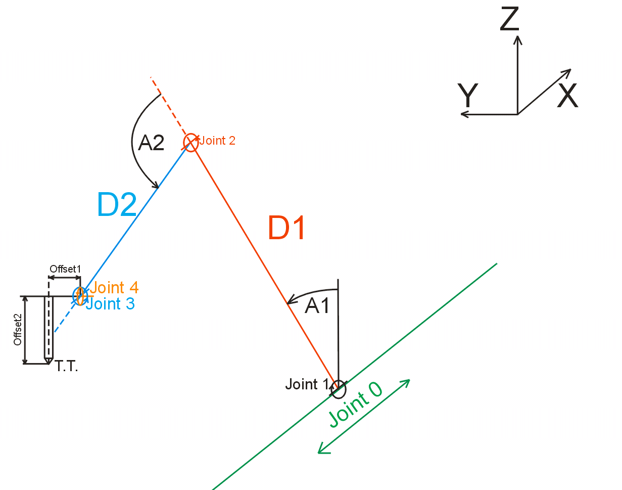
there are still many mysteries. Some are solved some still waiting to be solved. To understand how this kinematics work i drew some sketches.

First joints (joint 0, joint 1 and joint 2) are easy and well described for me as well as arm lenght D1 and elbow lenght D2. Joint 1 angle (A1) is easy too. Angle 0 means arm D1 is pointing upward as cartesian Z axis. Joint 2 angle (A2) is bit tricky to draw because it is described as:
joint[2] = Outer arm rotates around a horizontal axis at its inner end
which is attached to the outer end of the inner arm. A
value of zero means the outer arm is parallel to the
inner arm (and extending outward).
but later in C code a2 is denoted as a sum of a1 and a2.
D2 is self explainatory.
And now the harder part:
joint[3] = End effector rotates around horizontal axis, that is
parallel to previous rotation axis and also X axis.
A value of zero means that the tooltip (if offset from the axis)
is pointing in the same direction as the centerline of the outer arm.
Is centerline of the outer arm (elbow) correctly drawn in blue dashed line? what does it mean: "if offset from the axis"? in what direction? How to draw it? Is it Offset1 in my drawing below?
closer view:
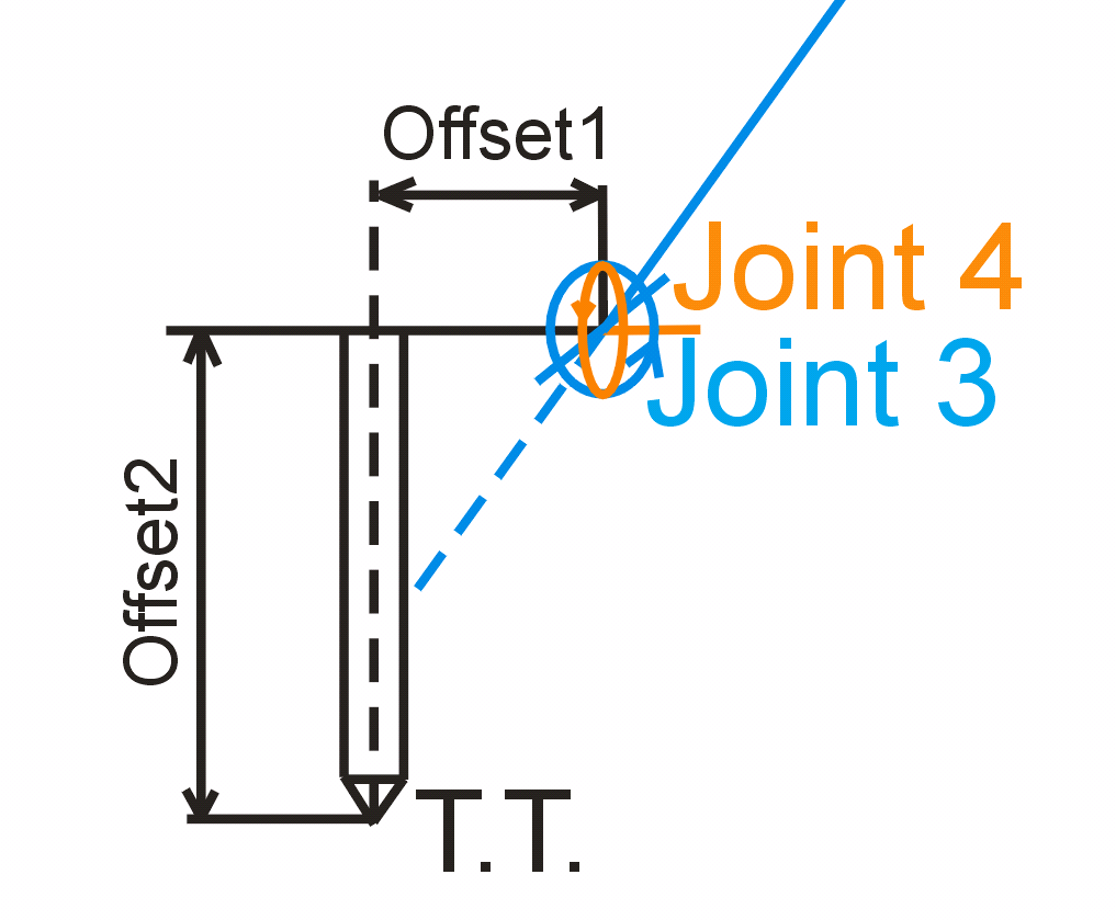
Above: joint 3 in blue reloves aroud axis parallel to cartesian X axis. Joint 4 in orange revoles aroud axis parallel to cartesian Y axis.
A value of zero means that the tooltip (if offset from the axis)
is pointing in the same direction as the centerline of the outer arm.
Does above tekst mean the situation in the drawing below:
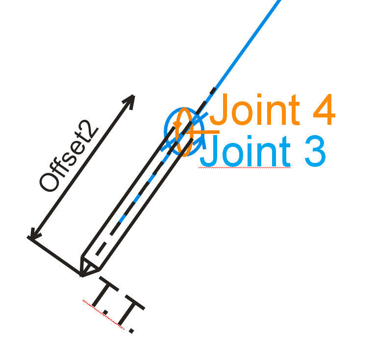
In fact Offset2 is D3 in robokins.c, right?
What if i use i.e. milling router instead of welding head. I will need change tool offsets (D3 parameters) for different bits. Is kinematics we are talking about here ready for it. D3 is fixed in INI file. Can it be changed 'on the fly' when tool change in G-code is needed?
What about Offset1 in my drawings? Is this distance matter assuming tha angle of joint3 always set the tool perpendicular to Y axis?
First joints (joint 0, joint 1 and joint 2) are easy and well described for me as well as arm lenght D1 and elbow lenght D2. Joint 1 angle (A1) is easy too. Angle 0 means arm D1 is pointing upward as cartesian Z axis. Joint 2 angle (A2) is bit tricky to draw because it is described as:
joint[2] = Outer arm rotates around a horizontal axis at its inner end
which is attached to the outer end of the inner arm. A
value of zero means the outer arm is parallel to the
inner arm (and extending outward).
but later in C code a2 is denoted as a sum of a1 and a2.
D2 is self explainatory.
And now the harder part:
joint[3] = End effector rotates around horizontal axis, that is
parallel to previous rotation axis and also X axis.
A value of zero means that the tooltip (if offset from the axis)
is pointing in the same direction as the centerline of the outer arm.
Is centerline of the outer arm (elbow) correctly drawn in blue dashed line? what does it mean: "if offset from the axis"? in what direction? How to draw it? Is it Offset1 in my drawing below?
closer view:
Above: joint 3 in blue reloves aroud axis parallel to cartesian X axis. Joint 4 in orange revoles aroud axis parallel to cartesian Y axis.
A value of zero means that the tooltip (if offset from the axis)
is pointing in the same direction as the centerline of the outer arm.
Does above tekst mean the situation in the drawing below:
In fact Offset2 is D3 in robokins.c, right?
What if i use i.e. milling router instead of welding head. I will need change tool offsets (D3 parameters) for different bits. Is kinematics we are talking about here ready for it. D3 is fixed in INI file. Can it be changed 'on the fly' when tool change in G-code is needed?
What about Offset1 in my drawings? Is this distance matter assuming tha angle of joint3 always set the tool perpendicular to Y axis?
Last edit: 15 May 2017 10:56 by Boogie.
Please Log in or Create an account to join the conversation.
Time to create page: 0.342 seconds