Mesa 5i25 config for chinese BOB
- andypugh
-

- Offline
- Moderator
-

- Posts: 19861
- Thank you received: 4636
but the menthality of the KNOWING people is so i know it an you can study
Most time only one line is wrong the erote a lot of text and post the shity documentation link
Yes, and I make no apology for this.
Bear in mind that none of us are paid to do this, all the time we spend answering questions on the forum is time that we are not spending working on our own projects.
It is far more efficient for _me_ to tell you how to solve your own problems than to solve every problem you have one at a time. If that is more work for you, then tough.
Please Log in or Create an account to join the conversation.
- Todd Zuercher
-

- Away
- Platinum Member
-

- Posts: 4742
- Thank you received: 1454
If you don't want to take the time to learn the software, pay someone to do it for you. Don't expect people to do your work for free (unless you work for the government.)
Please Log in or Create an account to join the conversation.
- pacman13b
- Offline
- New Member
-

- Posts: 15
- Thank you received: 1
Please Log in or Create an account to join the conversation.
- G0G53Z148
-
- Offline
- Senior Member
-

- Posts: 65
- Thank you received: 6
Post your Pinout for your bob may be so can help better
an link to your operating manual for bob or type store link or so
@Todd Zuercher what your comment mean have you programmed this?
@Andy
Why are you so aggressive and insulting just because there are people that English is not native language call her. if I do not help me to help but not not write. Give me a documentation I can read in my mother tongue and I do not bother you.
Had Linus also thought it was not for linux. If all who have worked on it does not respond as you would not schattendarsein run alongside Microsoft and its erfolgreciher. Back then appeared as Linux, it was far more advanced than Windows but has Komunity single axle drift gradually by arguing and senseless discussions.
I have spent in the last time a lot of money to get working configurations and these are all mediocre.
If I'm looking how to do it then I write at least one complete example with comments to so would also help subsequent users. But because the fronts have now already hardened, it is better you are looking at a different way.
Sure I can understand you it is annoying over and over again to discuss the same but do not you think it much more useful would be if you have the solution already written there to vwerseisen out as such on an awkward half-finished and hard-to-understand guide? I do not know if you've programmed with Linuxcnc
but the opinion I can also stand alone.
Please Log in or Create an account to join the conversation.
- Todd Zuercher
-
- Away
- Platinum Member
-
- Posts: 4742
- Thank you received: 1454
Please Log in or Create an account to join the conversation.
- pacman13b
- Offline
- New Member
-
- Posts: 15
- Thank you received: 1
1 – PWM - output
2 – STEP X - output
3 – DIR X - output
4 – STEP Y - output
5 – DIR Y - output
6 – STEP Z - output
7 – DIR Z - output
8 – STEP A - output
9 – DIR A - output
10 – E-STOP - input
11 – PROBE - input
12 – LIMIT X - input
13 – LIMIT Y - input
14 – ENABLE Drive (-) - output
15 – LIMIT Z input
16 – STEP B - output
17 – DIR B - output
18, 19, 20, 21, 22, 23, 24, 25 – GND
My step / dir & enable drive signals are (-)
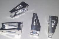
5 - AXIS Break out board.
Thank u.
Please Log in or Create an account to join the conversation.
- andypugh
-
- Offline
- Moderator
-
- Posts: 19861
- Thank you received: 4636
It looks like the only standard bitfile with PWM on Pin1 is DMMBob, and that has the step and direction pins switched compared to what you need.ended up with with the prb_rfx2 pin file flashed to mesa, but it seems like it is missing pwm on pin 1
That ought to be fairly easy, you just need to link a GPIO pin. However pin 14 on the RF1 bitfile is set up as the spindle PWM, so only becomes available as GPIO if you set num_pwmgens to zero in the config.and I couldn't program an enable pin for the drives also.
Does your BoB output an analogue voltage based on the PWM on Pin 1? If so then your simplest option is probably to use the dmmbob firmware and swap the step/dir wires at the drive end as apart from the switched step/dir lines that appears to suite your BoB well.
What sort of "not good" ? Depending on the drives you may need to invert the step pins to get the right sort of drive signal. Otherwise look at that step time setting.After manually enabling the drives I had some motion on axis x,y,z.but not good.
Please Log in or Create an account to join the conversation.
- G0G53Z148
-
- Offline
- Senior Member
-
- Posts: 65
- Thank you received: 6
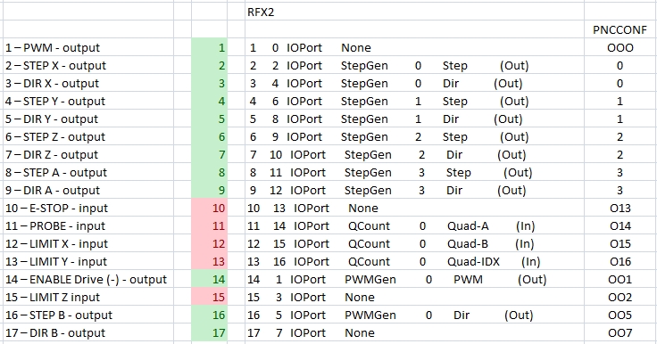
when you start pncconf you have to select the rfx2 firmware in pncconf after flashing the card and press accept
i have no computer here with linuxcnc on it you must a little improve
at the start configurating page of mesacard in pncconf you select 0 encoders then you can use the encoderpins for I/O
only the pwm you must bridge with an adaptor to the cross of the cable
i do not use pwm regulation
and then you canb klick any pins in the dropdown list
this is all i know about this sorry more help i cant give to you
the numbers at last 000: 1: 001: are the digital inside pins this are not the output pins this is important
the grean and red numbers in the pictures should be the Real pin numbers
if you want to have them others you have to seek an coder who makes a custom bitfile
i hope you help this to get it up
Please Log in or Create an account to join the conversation.
- pacman13b
- Offline
- New Member
-
- Posts: 15
- Thank you received: 1
")
Please Log in or Create an account to join the conversation.
- pacman13b
- Offline
- New Member
-
- Posts: 15
- Thank you received: 1
G0G53Z148 your post really helped me on getting the idea of how to map things out.. thank you.
The only thing I can't bypass and I'mm stuck is when testing for motor movement velocity etc. the motor moves but doesn't stop on time
maybe after a long while it keeps on moving and incrementing speed . can't seem to understand, step drivers are DQ860MA, maybe step time delay?? I tried different numbers up to 5000ms but same issue numbers below 2000ms don't run at all. DataSheet of driver say 2500, so I left it there.
Any ideas has anybody reference this situation.
If I do a motor test inside pcnconf +-50mm goes 50.5xx then it comes back to 50.0 with microsteps and vise versa.
The mesa fpga card is really high end. Keep up the excellent hardware r&d.. .
Thank you all for getting me up and running ..
Please Log in or Create an account to join the conversation.