Mesa 5i25 & 7i77: connecting encoder + one servo motor
- Konikoko
- Offline
- New Member
-

Less
More
- Posts: 4
- Thank you received: 0
11 Jul 2018 10:20 #114005
by Konikoko
Mesa 5i25 & 7i77: connecting encoder + one servo motor was created by Konikoko
Hello everyone,
I am new on this forum so if this is posted in the wrong section, I'm sorry.
I have a little bit of trouble connecting the 5i25 & 7i77 with my encoder (servo amplifier with simulated encoder output).
My servo amplifier is an IRT SA series 1000r. I have a bunch of cables I need to connect to the 7i77 that comes from this amplifier. There are two connectors that go out of the amplifier: I/O connector and the simulated encoder output.
The servo motor is already connected to the amplifier. The only thing I need to do now is to connect the amplifier with the 7i77 mesa board but I am not sure how to do it: the pin out for the I/O connector and the pin out for the simulated encoder are listed in the images below (see attachments). I have connected most of the encoder wires (see data sheet) but I don't know how to connect the I/O wires from the amplifier. Can you guys help me connecting this so I can try to turn my servo motor ? (I want to test the setup with one servo motor)
Thanks for this and sorry for my English. If this is a little bit unclear, please tell.
Please Log in or Create an account to join the conversation.
- RotarySMP
-

- Offline
- Platinum Member
-

Less
More
- Posts: 1627
- Thank you received: 595
12 Jul 2018 06:38 - 12 Jul 2018 06:52 #114045
by RotarySMP
Replied by RotarySMP on topic Mesa 5i25 & 7i77: connecting encoder + one servo motor
Hello Konikoko,
Here is my take on it...
Encoder:
You have a differential encoder, so the the three jumpers for that axis need to be in the default right hand position.
The 7i77 powers encoders with 5VDC. This is one of the options for powering your encoders - you will need to ensure your encoder is jumpered for 5V per your third attachment. The 7i77 can not provide enough current through through the cable from the 5i25 for multiple encoders. You need to provide sufficient 5V power on the 7i77 TB1 connector, and change the jumper W5 to the right hand postion, while ensuring the 5i25 jumper W1 and W2 are both in the down position (refer to the MESA manuals for which way is up and right)
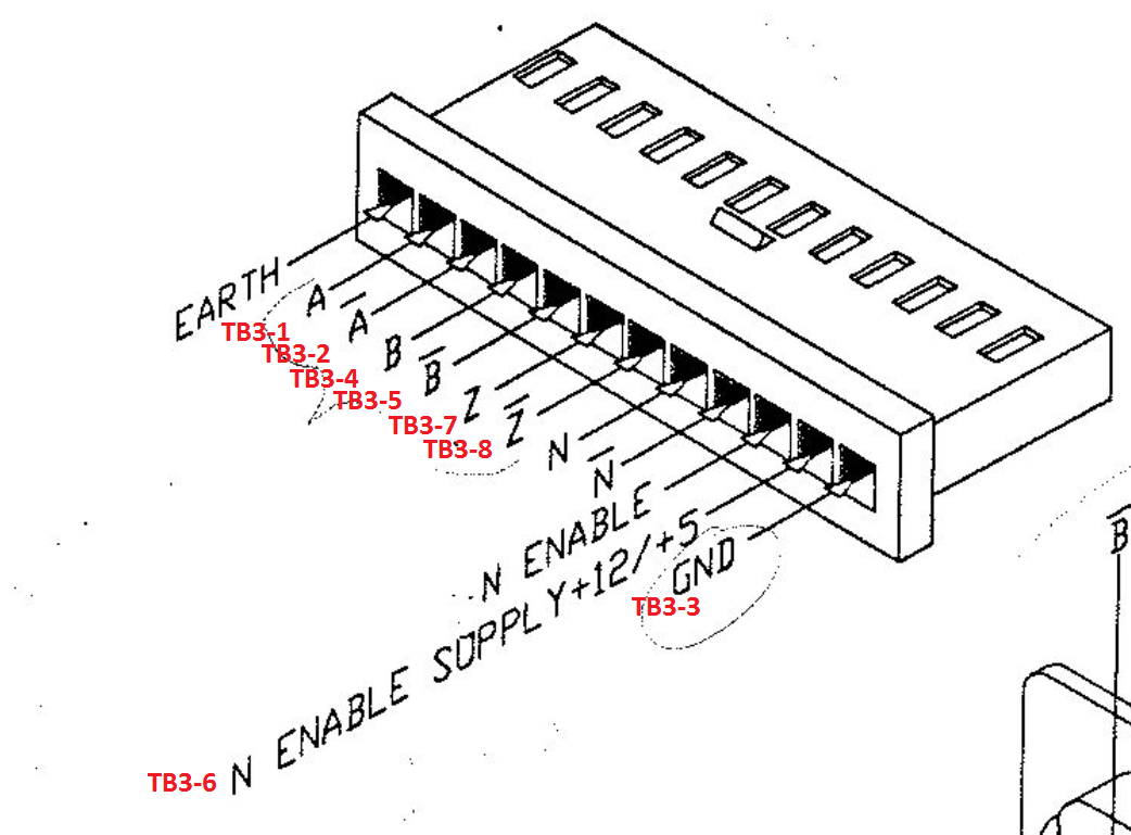
The first axis encoder connects to TB3 as follows:
Motor:
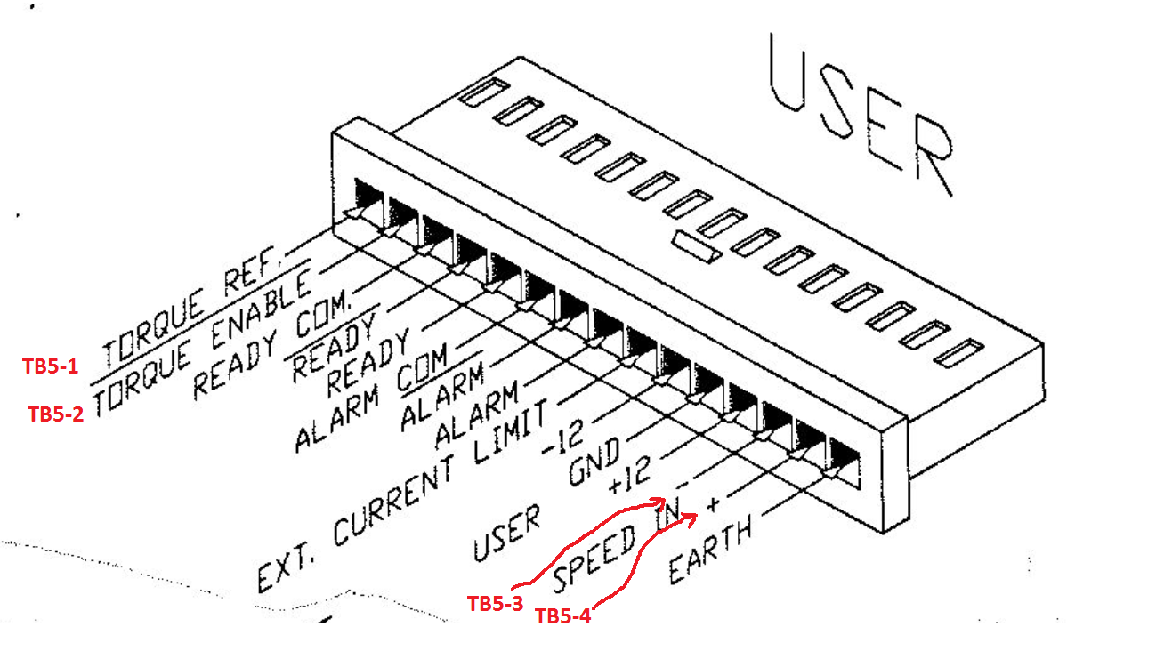
I also found MESA's description of the motor terminal assignment confusing. The paired pins for the +/-10V analog drive signals are on TB5 and called GND and AOUT10. So for the same axis as the encoder above...
Other pins such as the "Alarm", "Ready" are outputs from the driver module, which you should connect into LinuxCNC through general input pins such as TB7-1 through TB7-10, and then set up your INI and Config files to trigger E Stop on "Alarm" for example.
Mark
Here is my take on it...
Encoder:
You have a differential encoder, so the the three jumpers for that axis need to be in the default right hand position.
The 7i77 powers encoders with 5VDC. This is one of the options for powering your encoders - you will need to ensure your encoder is jumpered for 5V per your third attachment. The 7i77 can not provide enough current through through the cable from the 5i25 for multiple encoders. You need to provide sufficient 5V power on the 7i77 TB1 connector, and change the jumper W5 to the right hand postion, while ensuring the 5i25 jumper W1 and W2 are both in the down position (refer to the MESA manuals for which way is up and right)
The first axis encoder connects to TB3 as follows:
Motor:
I also found MESA's description of the motor terminal assignment confusing. The paired pins for the +/-10V analog drive signals are on TB5 and called GND and AOUT10. So for the same axis as the encoder above...
Other pins such as the "Alarm", "Ready" are outputs from the driver module, which you should connect into LinuxCNC through general input pins such as TB7-1 through TB7-10, and then set up your INI and Config files to trigger E Stop on "Alarm" for example.
Mark
Last edit: 12 Jul 2018 06:52 by RotarySMP.
The following user(s) said Thank You: Konikoko
Please Log in or Create an account to join the conversation.
- Konikoko
- Offline
- New Member
-
Less
More
- Posts: 4
- Thank you received: 0
12 Jul 2018 11:56 #114049
by Konikoko
Replied by Konikoko on topic Mesa 5i25 & 7i77: connecting encoder + one servo motor
This is exactly what I needed, I can't thank you enough Mark.
However, I encountered another problem.
I tried loading two simple configurations files and they both failed with the following errors (see attachments (error-configuration-johntron and error-mesa-configuration) for more details):
HAL: ERROR: function 'hm2_5i25.0.pet_watchdog' not found
./7i77.hal:30: addf failed
HAL: ERROR: function 'hm2_5i25.0.pet_watchdog' not found
./hm2-servo7i77.hal:64: addf failed
The configuration files came from this site: John Thornton Tutorial
I also tried pncconf to create my own configuration files but I failed with the following error (error-machinebuild.txt in attachments):
./machinebuild1.hal:50: parameter or pin 'hm2_5i25.0.7i77.0.1.analogout0-scalemax' not found
6792
So I think there is a problem with the communication between the 5i25 and the 7i77.
I supplied 5v to TB1 and 12v to TB2 (4 pins with all the jumpers are properly configured).
On the 7i77 board, the following leds are on: CR1 (yellow), CR6 (yellow), CR7 (yellow), CR3 (yellow) and CR16 (red).
Also I should note that there is a MESA 7i77ISOL galvanic isolator between the 7i77 and the 5i25 (it came with it when we purchased the kit). All leds are turned off on the MESA 7i77ISOL galvanic isolator board.
Please Log in or Create an account to join the conversation.
- PCW
-

- Offline
- Moderator
-

Less
More
- Posts: 17954
- Thank you received: 5261
12 Jul 2018 14:53 - 12 Jul 2018 14:53 #114065
by PCW
Replied by PCW on topic Mesa 5i25 & 7i77: connecting encoder + one servo motor
The watchdog error is because Johns example is for LinuxCNC 2.6 and earlier
to use his example simply delete or comment out the "addf pet_watchdog servo-thread" line in the hal file
When you use the galvanic isolator you must set the FPGA card to power the 7I77 (its actually just powering its side of the isolator) and set the 7I77 to accept FPGA power (so it can back-power the isolator on the 7I77 side) You must still provide 5V to TB1
www.mesanet.com/pdf/parallel/7i77isolman.pdf
Note the section about setting the multiplex rate for the isolator
I suggest you set the multiplex rate to 3 or 4 MHz as shown in the manual and do not set the skew as there's a bug in the current skew setting method in the driver
Last edit: 12 Jul 2018 14:53 by PCW.
The following user(s) said Thank You: Konikoko
Please Log in or Create an account to join the conversation.
- Konikoko
- Offline
- New Member
-
Less
More
- Posts: 4
- Thank you received: 0
12 Jul 2018 15:36 #114071
by Konikoko
Replied by Konikoko on topic Mesa 5i25 & 7i77: connecting encoder + one servo motor
Thanks for the clarification PCW.
I removed the isolator but I will add it tomorrow.
I commented out the "addf" line and everything seems to work out now.
The encoder is connected properly and I think the drive too (I followed Mark's advice).
When I start the configuration made by mesa (or Johns example), AXIS starts with the configuration file loaded.
In AXIS I can move the motor for a little bit but I always get the joint 0 following error.
I suppose the next step is to create a configuration with pncconf and to follow this guide? Guide
Or is there something that should be done first?
Please Log in or Create an account to join the conversation.
- andypugh
-

- Offline
- Moderator
-
Less
More
- Posts: 19875
- Thank you received: 4641
16 Jul 2018 14:37 #114303
by andypugh
Replied by andypugh on topic Mesa 5i25 & 7i77: connecting encoder + one servo motor
I am not sure that, in this setup you would use the encoder power supply pins on the 7i77 at all. If the encoder connects to the drive and then the drive send out "repeater" signals then the drive is powering the encoder.
Please Log in or Create an account to join the conversation.
- Konikoko
- Offline
- New Member
-
Less
More
- Posts: 4
- Thank you received: 0
18 Jul 2018 09:35 #114457
by Konikoko
Replied by Konikoko on topic Mesa 5i25 & 7i77: connecting encoder + one servo motor
Hello everyone,
I figured everything out. I will list all the connections I made in this topic so that others can benefit from this.
The setup is for an IRT SA CH-2005 Neuchatel servo amplifier with the 5i25/7i77, one servo motor and one mpg.
TB3 ENC 0
QA0 ---> A (from servo amplifier)
/QA0 ---> /A
GND ---> GND
QB0 ---> B
/QB0 ---> /B
+5v ---> nothing (has its own power)
IDX0 ---> Z
/IDX0 ---> /Z
TB2 Field:
1,2,3,4 ---> 12v power supply (W1 in default left hand position).
GROUND ---> GND and END SWITCH 1 & 2 (from servo amplifier), MPG 0V (from MPG)
TB5 DRIVE 0:
ENA0- ---> Torque Ref
ENA0+ ---> Torque Enable
GND ---> +Speed
AOUT0 ---> -Speed
I/O TB7
16 ---> MPG A
17 ---> MPG B
The mpg was installed by enabling mode 3 in PNCconf.
Everything works but there is one thing that bothers me.
I can't select the jog increments in the axis GUI.
Any ideas on how I can achieve this? (maybe I should start a new topic in the GUI section?)
Thanks a lot to everyone who replied in this topic
Please Log in or Create an account to join the conversation.
- andypugh
-
- Offline
- Moderator
-
Less
More
- Posts: 19875
- Thank you received: 4641
23 Jul 2018 09:03 #114688
by andypugh
Replied by andypugh on topic Mesa 5i25 & 7i77: connecting encoder + one servo motor
Do you mean that jog increment selection in Axis is disabled, ineffective or unaware of external changes?
Please Log in or Create an account to join the conversation.
- Marki123
- Offline
- Senior Member
-

Less
More
- Posts: 48
- Thank you received: 1
30 Dec 2018 09:58 #123137
by Marki123
Replied by Marki123 on topic Mesa 5i25 & 7i77: connecting encoder + one servo motor
Hello everybody. I also have a problem with the Mesa 5i25 & 7i77 wire connection with the encoder properly connect right to the 7I77. I would like to try the servo. Maybe someone can help me out of you. And sorry for my english
Please Log in or Create an account to join the conversation.
- PCW
-
- Offline
- Moderator
-
Less
More
- Posts: 17954
- Thank you received: 5261
30 Dec 2018 13:36 #123146
by PCW
Replied by PCW on topic Mesa 5i25 & 7i77: connecting encoder + one servo motor
7I77     ENCODER
QA0       A
/QA0     /A
GND       GND
QB0       B
/QB0     /B
+5V      +5V
IDX0      N
/IDX0    /N
The following user(s) said Thank You: Marki123
Please Log in or Create an account to join the conversation.
Moderators: PCW, jmelson
Time to create page: 0.190 seconds