Retrofitting maho mh 1000t
- Sourabh3
- Offline
- Senior Member
-

Less
More
- Posts: 73
- Thank you received: 1
01 Feb 2021 08:44 #197288
by Sourabh3
Replied by Sourabh3 on topic Retrofitting maho mh 1000t
This was strange for me too. But seeing at the schematics and other few examples, this is how it looks like to be connected. U and v both are connected to +200v and A will drive the motor. You can see, i have posted pics of manual earlier. I just want to test it, so that I can move forward to mesa cards.
Please Log in or Create an account to join the conversation.
- Sourabh3
- Offline
- Senior Member
-

Less
More
- Posts: 73
- Thank you received: 1
01 Feb 2021 08:48 #197289
by Sourabh3
Replied by Sourabh3 on topic Retrofitting maho mh 1000t
I have the manual but it's being a little hard for me(rookie). Do you have any new idea? Perhaps can you please check with your maho? Maybe we can find out what's wrong.
Please Log in or Create an account to join the conversation.
- andypugh
-

- Offline
- Moderator
-

Less
More
- Posts: 19760
- Thank you received: 4589
02 Feb 2021 00:19 #197354
by andypugh
Replied by andypugh on topic Retrofitting maho mh 1000t
I think that is it very likely that the drive will fault-out without the mtor tacho connected. That is what closes the velocity loop, and the drive can't really work without it.
Please Log in or Create an account to join the conversation.
- Sourabh3
- Offline
- Senior Member
-

Less
More
- Posts: 73
- Thank you received: 1
11 Feb 2021 04:59 #198350
by Sourabh3
Replied by Sourabh3 on topic Retrofitting maho mh 1000t
Rookie mistake... I didn't check the fuse..... I changed it and now it's working.... I have 450v ac 3 phase supply.... So dc 33 volts were being fed to 3trm2 circuit... And the fuse was rated only for 30v.....
Please Log in or Create an account to join the conversation.
- Sourabh3
- Offline
- Senior Member
-

Less
More
- Posts: 73
- Thank you received: 1
11 Feb 2021 05:03 - 11 Feb 2021 05:09 #198351
by Sourabh3
Replied by Sourabh3 on topic Retrofitting maho mh 1000t
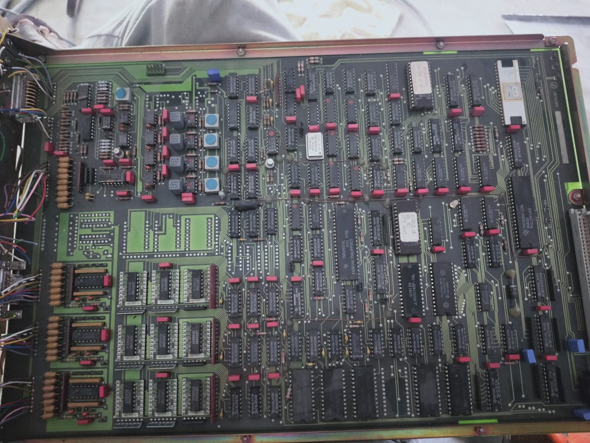
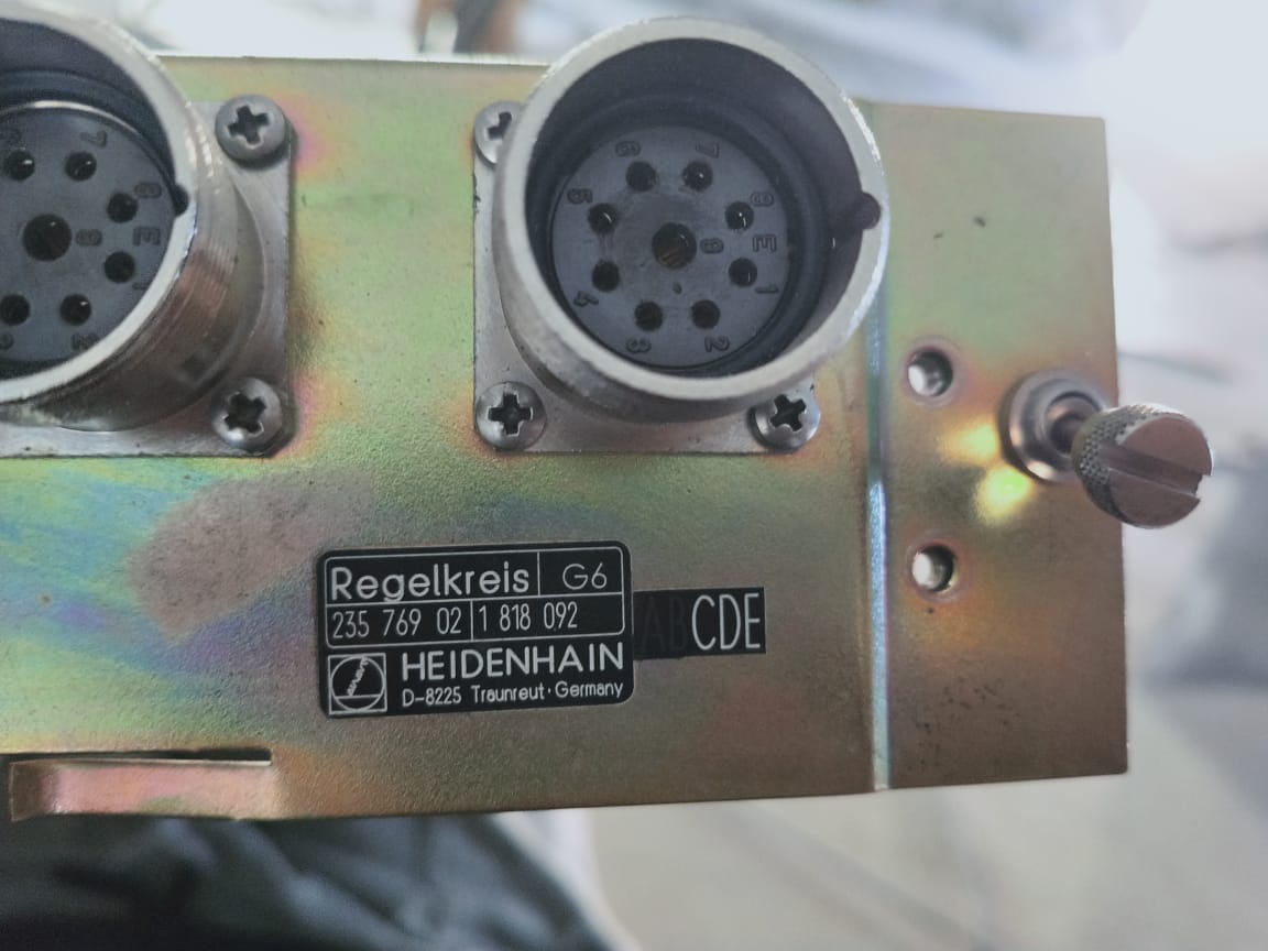
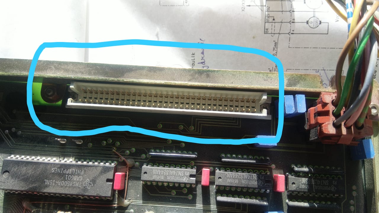
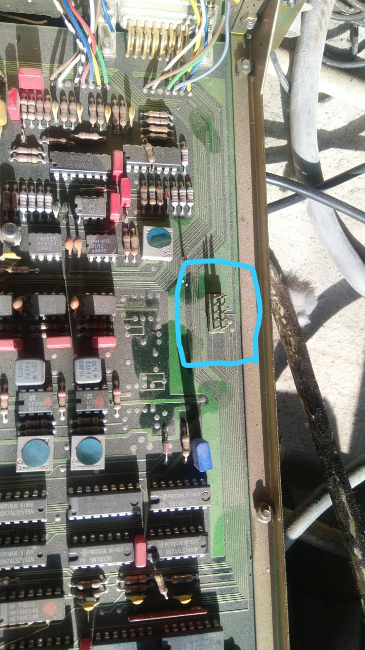
Hey Mark.... I was watching your video and you talked about recycling linear Encoder interpolation card from 432. I have a 332 cnc and the card is regelkreis g6. I can't find any document related to it on the internet. I'm attaching the picture... Maybe you can have a look at it and let me know if i can connect it with 7i84?
Cheers
Sourabh
Cheers
Sourabh
Attachments:
Last edit: 11 Feb 2021 05:09 by Sourabh3.
Please Log in or Create an account to join the conversation.
- J Green
- Offline
- Elite Member
-

Less
More
- Posts: 164
- Thank you received: 24
11 Feb 2021 07:35 #198363
by J Green
Replied by J Green on topic Retrofitting maho mh 1000t
Sourabh
Your -- 332 cnc and the card is Heidenhain regelkreis g6 ? I wonder if your machine is using the Phillips linear scales vers the Heidenhain linear scales !
Could you take a photo an show one of the scales label ? The " Y " axis scale ( axis having the vertical-horizontal spindle ) is usually the easiest to look at or get to .
The transformers an chokes powering the Indrament SCR drives are specific to the servo motors an drive performance . So in your conversion I would suggest keeping them. Also, as Mark has mentioned replacing DC capacitors is a good consideration .
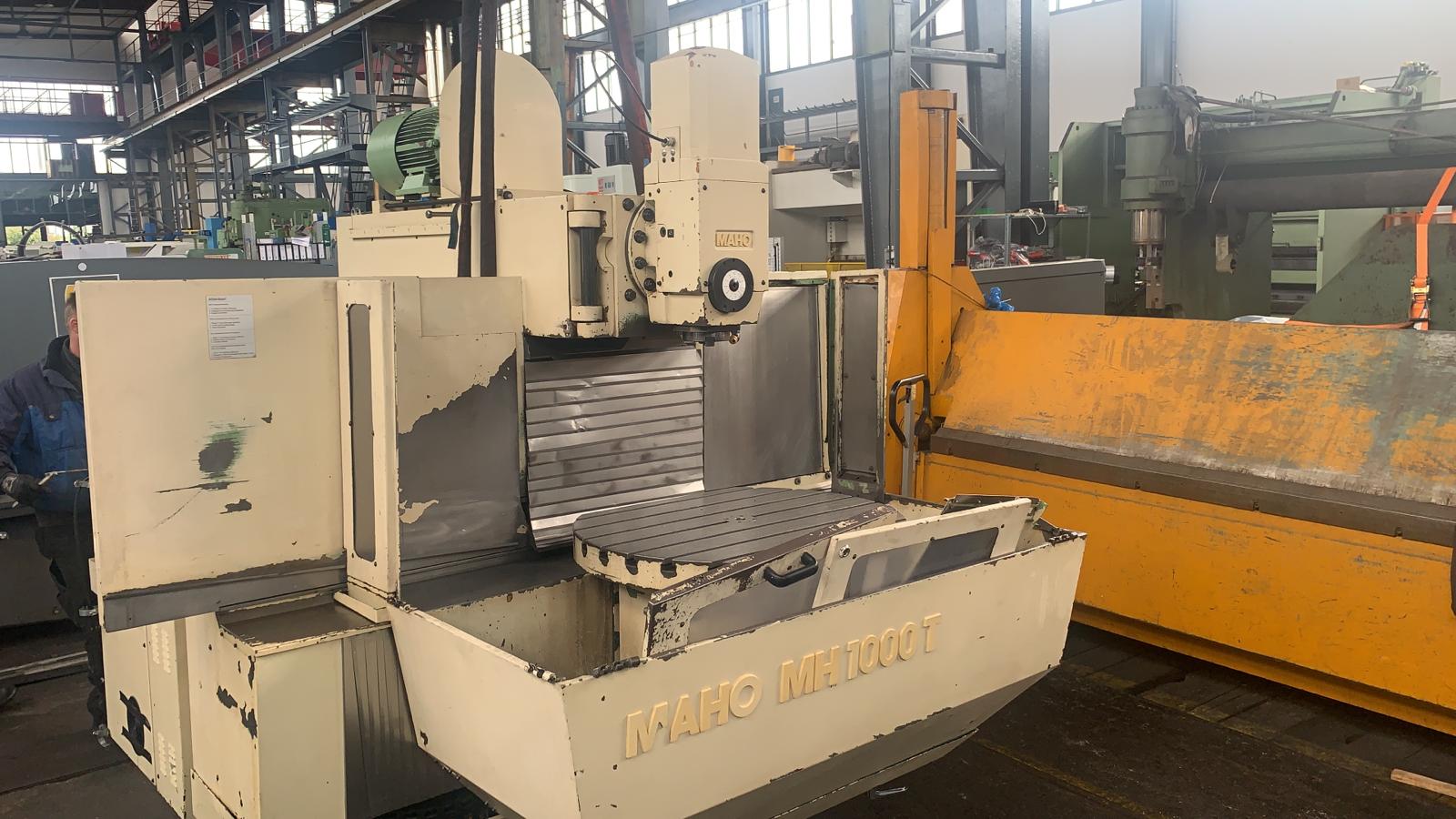
How about some Photos of your Maho machine and it's control counsel ? Would be quite useful to current and future viewers to this conversion of your machine .
Bob
The following user(s) said Thank You: RotarySMP
Please Log in or Create an account to join the conversation.
- RotarySMP
-

- Offline
- Platinum Member
-

Less
More
- Posts: 1537
- Thank you received: 568
11 Feb 2021 08:04 - 11 Feb 2021 08:09 #198365
by RotarySMP
Replied by RotarySMP on topic Retrofitting maho mh 1000t
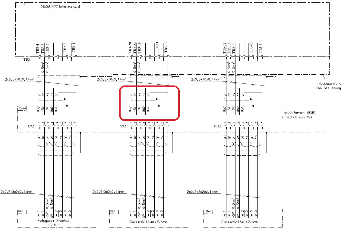
That card is completely diffent to the one which A/D converts my Heindenhein scales. It is a good pick up by Bob that this machine might have Phillips scales. Maho used them in that era. I know of no one who has been able interface those cards. Muellernick on the Zerspannungsbude but a lot of effort into deocoding the interface but was not able to. He replaced his scales with modern TTL scales.
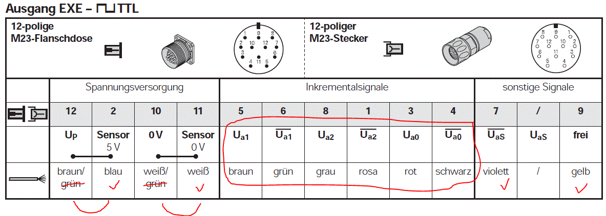
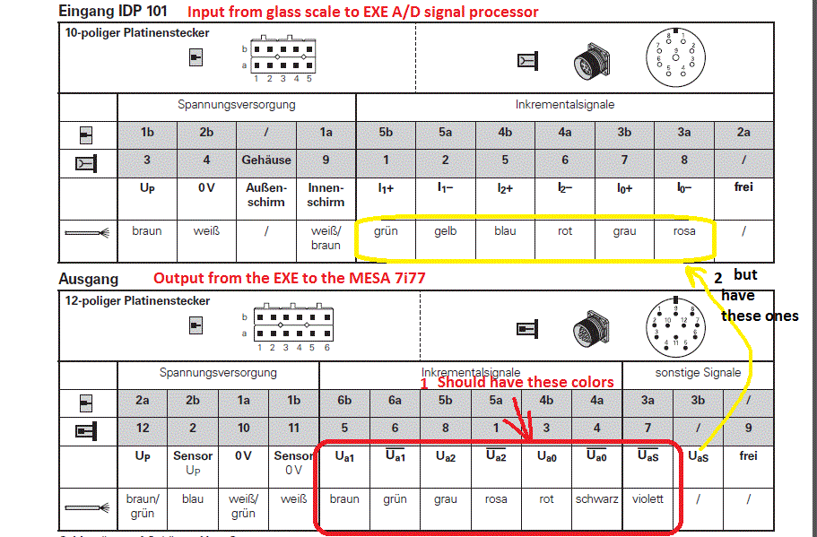
If your scales are Heidenhain, you will find that Heidenhain hs been very consistant with wire color for decades. It doesn't seem to matter much which generation of EXE dtasheet you look at.
In my case my three axis board turned out to have have one completely dead channel, and a second channel which is unreliable. So in practice it is only lane attached to one scale now. The other two have stand alone 602 EXE's which i bought off Ebay.de. One interesting thing is that the three axis board needs both 5V and 12V to each channel, and are only wired to output a single ended signal, whereas the stand alone modules only need 5V and are wired to poutput the full differential signal. Had I known then that the 3 axis board had issues, I would have simply bought three 602's. Just note that some 602's output 5µm resolution, while others output 1µm.
Mark
If your scales are Heidenhain, you will find that Heidenhain hs been very consistant with wire color for decades. It doesn't seem to matter much which generation of EXE dtasheet you look at.
In my case my three axis board turned out to have have one completely dead channel, and a second channel which is unreliable. So in practice it is only lane attached to one scale now. The other two have stand alone 602 EXE's which i bought off Ebay.de. One interesting thing is that the three axis board needs both 5V and 12V to each channel, and are only wired to output a single ended signal, whereas the stand alone modules only need 5V and are wired to poutput the full differential signal. Had I known then that the 3 axis board had issues, I would have simply bought three 602's. Just note that some 602's output 5µm resolution, while others output 1µm.
You don't. The encoder signals need to be connected to the dedicted encoder inputs of the 7i77 (or 7i97)Maybe you can have a look at it and let me know if i can connect it with 7i84?
Mark
Attachments:
Last edit: 11 Feb 2021 08:09 by RotarySMP.
Please Log in or Create an account to join the conversation.
- Sourabh3
- Offline
- Senior Member
-

Less
More
- Posts: 73
- Thank you received: 1
11 Feb 2021 09:20 #198370
by Sourabh3
Replied by Sourabh3 on topic Retrofitting maho mh 1000t
Hello bob,
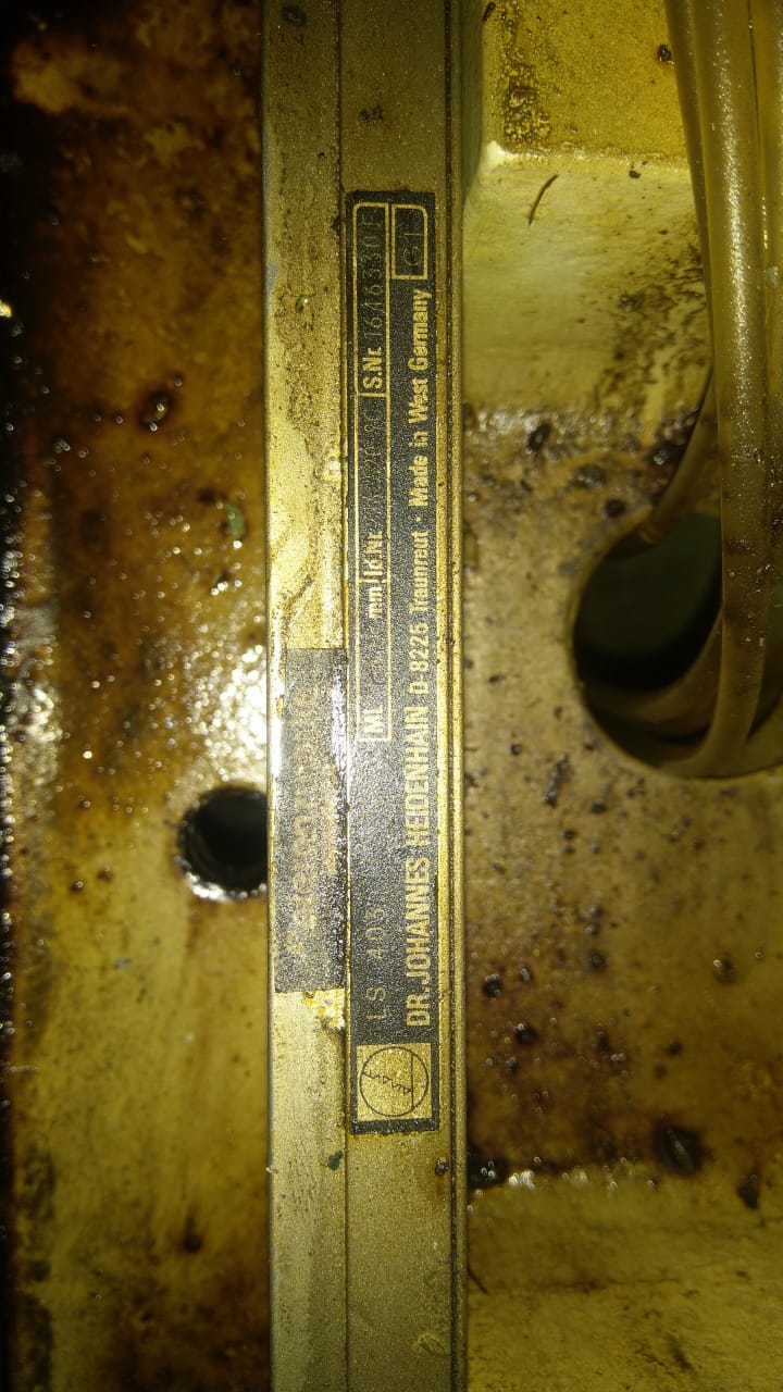
Yes, I'm keeping the choke and the 3trm2 drives as it is. I'm attaching the details of heidenhain scales that my machine have with pictures.
All are Dr. Johannes heidenhain LS403
Rest of the details for LS403 are as follows:
1. ML 620mm
Id. Nr. 226 520 8Z
S.Nr. 1946356G
G11
2. ML 720mm
Id. Nr. 226 520 9A
S. Nr. 2060066G
F13
3. ML 1140mm
Id.Nr. 226 520 9C
S. Nr. 1646330F
G1
Please suggest me a way so that i can re use this card with 7i77
Attachments:
Please Log in or Create an account to join the conversation.
- Sourabh3
- Offline
- Senior Member
-

Less
More
- Posts: 73
- Thank you received: 1
11 Feb 2021 09:29 #198371
by Sourabh3
Replied by Sourabh3 on topic Retrofitting maho mh 1000t
Attachments:
Please Log in or Create an account to join the conversation.
- RotarySMP
-

- Offline
- Platinum Member
-

Less
More
- Posts: 1537
- Thank you received: 568
11 Feb 2021 09:44 #198372
by RotarySMP
Replied by RotarySMP on topic Retrofitting maho mh 1000t
Well that is good news, LS-403's output the typical 11µA sinus wave analog signal, which the EXE's convert.
Could you please post a photo of the whole of the connector panel fo G6? Dust that board down, and look for test points for GND, +5VDC and +12VDC.
I can see two options for you. Without any data on that G6 card:
Option 1, search the board for +5Vdc, possible +12Vdc and ground signals, and follow them back to the 32 pin connector. Once you can get the board powered up, everything else coming out of that connector is going to be a TTL encoder or index signal, so from there it would just be the painstaking work to systematically probe them with an Osci, and work out which pin is whch channel and channel. Heidenhain is very systematic. You might quite quickly identify the sytem of pin assignment. With that generation of electronics, the traces are pretty large, so you may be able to map pins to traces to functions quite easily.
Option 2, spend about €250 and get three EXE's off ebay (search Heidenhain EXE) , and dump the G6 board. The only thing which is tricky is working out the jungle of Heindenhain 600 EXE numbering to get the ones with 1µm resolution. Although one of mine is 5µm, and that is fine for my machining level.
Mark
Please Log in or Create an account to join the conversation.
Moderators: PCW, jmelson
Time to create page: 0.195 seconds

