Light Machine Corp. Benchman XTr (retrofit)

More
11 years 11 hours ago #64565 by MacGalempsy
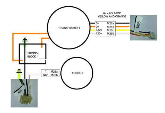
Here is the schematic I came up with for the High DC power loop. the M26 connector is the AC in and the M5 is the DC out. I ran the DC to a terminal block then connected them to each of the Amps. It works pretty well.

Please Log in or Create an account to join the conversation.

More
11 years 11 hours ago #64566 by MacGalempsy
dont forget a fuse between the DC out and the common terminal block!

Please Log in or Create an account to join the conversation.

More
10 years 11 months ago - 10 years 11 months ago #64599 by steve_a
Thanks again Mac. Your research is fantastic!
Last edit: 10 years 11 months ago by steve_a. Reason: wrong attachment

Please Log in or Create an account to join the conversation.

More
10 years 11 months ago - 10 years 11 months ago #64792 by steve_a
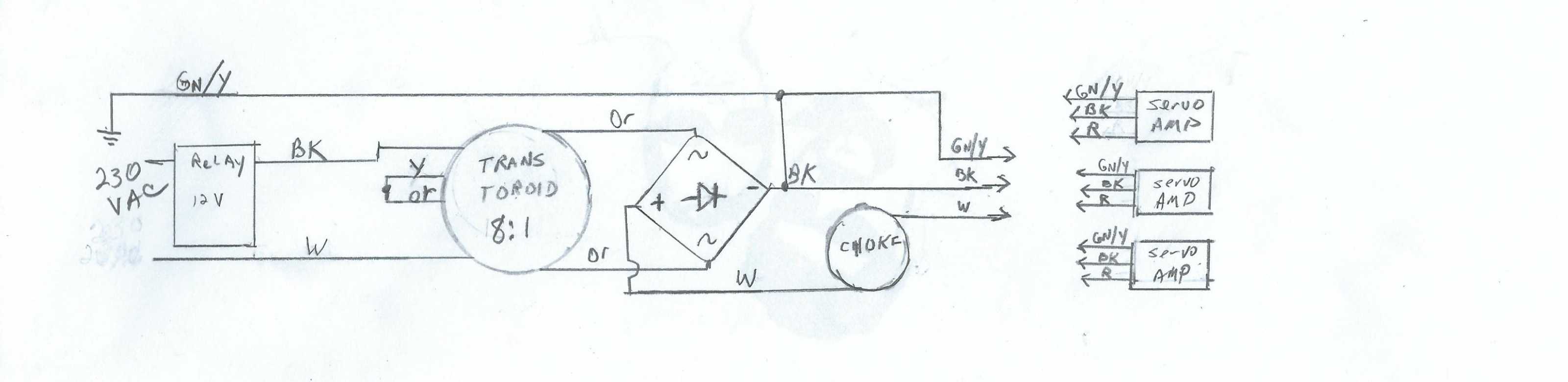
I have been working on preparations to do the controller swap and ordering a few parts I think I will need. While I was at it I decided to look closer at the drive supply. I did a quick ohm check of the BAT (Big A__ Toroid) and saw appox .8 ohm on both the input coils. I hadn't noticed before but there is only 1 output coil. ( I can only assume that is because this is a custom built toroid specifically for Light Machines and they designed it specifically for this machine.) The output showed about .2 ohms. Since the two .8 input coils are tied in series that makes an equivalent 1.6ohm coil making the input to output ratio 1.6/2 or 8:1. That gives 230V/8 = 28.75 V out. That seemed really small to me so I looked at the motors.
It turns out that My Z axis motor is a Moog C23-L50W20M09 and I believe the X and Y are the same. I looked at the Copley Controller information and noticed there are components added to match the motor to the controller. Page 5 shows what the components do and what values are needed. I found the RH15 resistor and determined it's values to be 402K which matches with model 4122 controller for a 1.8 to 4.8 mH Armature Inductance. Next I referenced the C23 series Motor specs. www.moog.com/literature/MCG/moc23series.pdf from Moog. The Motor shows an inductance of 1.96 Mh, in the correct range so I'm sure this is all set up correctly.
OK the reason I think all this is important is because I was wondering why the BAT looks like it will only source a calculated 28.75V. The motor specs shows that his motor is tolerant from 12-60V and rated for 24V. That seems to confirm my ohm measurements. Additionally, the Copley Controller operates from 22V to 90V.
So things are pointing to a 24V system. At least that's MY model with a 5000RPM spindle. Here's what I believe the drive supply looks like. (OOPS! wrong ratio... should be 8:1... I'll redraw and resubmit.)
I'm still waiting for my MESA controller so I am a bit stuck for now... I guess I could bypass the enable relay and see if I get 24V. Otherwise, I'm kind of at a standstill for now but I guess I need to find a relay board SO I think I will work on that.

Last edit: 10 years 11 months ago by steve_a. Reason: wrong attachment

Please Log in or Create an account to join the conversation.

More
10 years 11 months ago #64805 by andypugh

steve_a wrote: saw appox .8 ohm on both the input coils. I hadn't noticed before but there is only 1 output coil. ( I can only assume that is because this is a custom built toroid specifically for Light Machines and they designed it specifically for this machine.) The output showed about .2 ohms. Since the two .8 input coils are tied in series that makes an equivalent 1.6ohm coil making the input to output ratio 1.6/2 or 8:1. That gives 230V/8 = 28.75 V out


Unless the primary and secondary are wound with exactly the same size of wire a resistance check won't tell you the transformer ratio.

Have you tried turning on the power and measuring the output voltage?

Please Log in or Create an account to join the conversation.

More
10 years 11 months ago #64833 by steve_a
Good point andypugh. I could be totally off base on this. I have powered the unit up but there is no voltage coming out of the servo supply Without a functioning Nextmove card the main control pca in the Benchman will not enable the servo power by energizing the relay. I will have to jump the primary windings and bypass the relay. I think I can safely do that if I disconnect the output from the servo supply connection point since it is just a connector. However, the rectifier needs to be loaded to regulate. I might try it to see if the choke and VOhm meter will be enough of a load. Otherwise I might have to throw a resistor across the output.
My observations were based on my probing and since the toroid is not marked with any information regarding in and out voltages I went ahead and did the ratio calculation to try to verify the voltage I might see. Still, if the motors are rated for 24V, the 28.75V seems a reasonable number. The motor data sheet has two specs; the Rated Terminal Voltage 12-60V and the Terminal Voltage 24V. I took this to mean Tolerance and Operating Voltage, however, I am not shy to admit my ignorance and say that is just an ewag. It may actually be saying that the motors will operate in the range of 12 - 60V and is optimal at 24V. Even so I would think a company would design for optimal. I'll work on doing the test. You are correct in pointing out the wire size issue. Thanks for your input.

Please Log in or Create an account to join the conversation.

Time to create page: 0.312 seconds
Powered by Kunena Forum