RB1-CNC Retrofit
- LearningLinuxCNC
-
 Topic Author
- Offline
- Elite Member
-

Less
More
- Posts: 319
- Thank you received: 48
17 May 2015 19:54 #58789
by LearningLinuxCNC
RB1-CNC Retrofit was created by LearningLinuxCNC
Hello everyone. I am going to retrofit the cnc controls on my Sieber Hegner RB1-CNC machine. I will give you a little background on the entire project then I intend to use this thread to document the retrofit process hoping it may help someone looking to do a similar project in the future.
Background:
First off I am a mechanical engineer and I have some experience with CNC. 4 years ago I built a CNC router that runs on Mach 3 off the paralell port. I also have some experience with electronics. I have made several projects based on Arduino and I have worked on ultrasound probes for neurosurgery and plant instrumentation etc. in my career.
Enough about me, lets move on to the machine. The machine that I am retrofitting is a 3 axis milling machine. It is a bed mill with a counterweighted z axis. It currently has the original General Numeric (Fanuc/Siemens) control system installed. I purchased the machine about 1 month ago. Prior to purchasing it I was able to test several things on the machine to see if it was usable in its current form. I was able to move all of the axis, run a simple program that was already on the controller, start and stop the spindle and coolant pump. The issue came when I was trying to transfer data to the Fanuc controller. I had serial communication out of the controller but I could not send data to the controller.
I decided to purchase the machine and try to figure out why the serial communications would not work. I got the machine home and spent a couple weeks troubleshooting the problem. Once I had the machine home I realized that some of the chips from the milling process had made there way into the control cabinet that houses the main contol pcb for the Fanuc controls. I removed the board and cleared away any debris from the board. I did some more troubleshooting and even replaced the serial communication chips that were on the board with new ones. All of this was to no avail. Apparently the debris that was on the board had damaged an IC further into the board than the rs-232 reciever and transmitter chips.
I researched options to fix the machine. I could replace the Fanuc board with a like 25 year old used board of ebay for $750.00 or I could retrofit the machine to LinuxCNC. The machine in its current state runs off of 230V 3phase. I don't have that in my shop so I have to use a rotophase. One of the benefits of the LinuxCNC conversion is that I could remove the 3phase and convert to single phase using VFD's for the spindle and coolant motors as the servo drives would run off single phase with the conversion. After much debating and research here I am beginning the retrofit process.
During the research process I came across Pico Systems and Jon Elson. As it turned out Jon is about 1.5 hours away from where I live. I gave Jon a call and we discussed options for the project. He said that we could go with the PPMC and retain the existing servo drives, or we could use the PWM board and use his PWM servo drives. The biggest issue at the early stages of this decision was if the Pico brushless servo drives would be compatable with the Siemens servo motors that were on the machine. I tried to find as much data on the Siemens servo system as I could. I would send this information to Jon and we would both review it. After much research I thought I had enough data so that we could at least attempt a test on the servo motors. I removed the X-axis motor from my machine and took it to Jon's place. We were able to test the motor using Jon's test rig. We determined the proper wiring for the hall sensors vs the motor phase and the motor was off to the races.
All that was left to do was order some equipment. From Pico Systems I ordered the Universal PWM servo control board, Eight solid state relays for the board, 3 brushless servo drives, a heat sink and a spindle control board to control the speed of the spindle with the VFD. I ordered two VFDs for the spindle and coolant pump. I ordered a new pc motherboard, memory and a solid state hard drive. I purchased a touch screen monitor.
Yesterday I made my first real steps in the conversion. I made mounting plates for the monitor and other controls to go on the main operator contol panel. I made mountig brackets for the Pico Systems servo drives. I assembled the pc components in an old case that I had laying around. I installed the LinuxCNC 2.6 install on the new PC and I am now typing this post on that PC.
I will update this post with pictures of the machine and some videos of some of the retrofit components as I make progress.
I want to thank everone involved in this project. Especially Jon Elson he has gone out of his way to answer my questions, test my motor and make sure that the equipment I purchased from him would work for the project at hand. I also want to thank all of the programmers and contributors to the LinuxCNC project. What an awesome effort.
To Be Continued ...
Jim
Please Log in or Create an account to join the conversation.
- LearningLinuxCNC
-
Topic Author
- Offline
- Elite Member
-
Less
More
- Posts: 319
- Thank you received: 48
18 May 2015 06:54 #58805
by LearningLinuxCNC
Replied by LearningLinuxCNC on topic RB1-CNC Retrofit
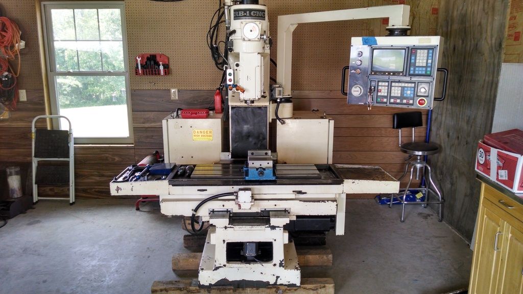
Here are the before pictures.
One of the machine as a whole.
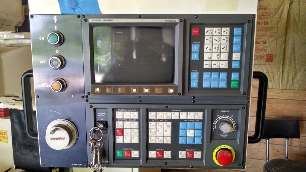
The Fanuc operators panel.
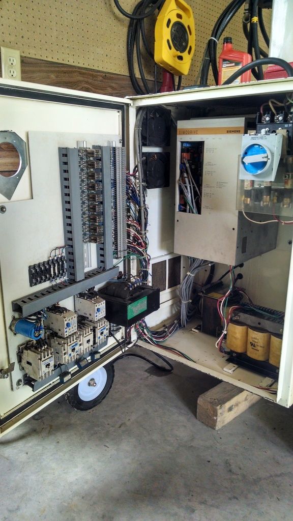
The power cabinet with the Siemens servo controller.
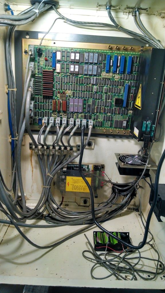
The control cabinet with the Fanuc OM-A main board and associated connections. I plan on keeping all of the cabling the same. Since the main board is bad I am going to rob the connectors from the board to make my connections to the Pico Systems Universal PWM Servo card. Should keep the layout pretty well organized that way.
One of the machine as a whole.
The Fanuc operators panel.
The power cabinet with the Siemens servo controller.
The control cabinet with the Fanuc OM-A main board and associated connections. I plan on keeping all of the cabling the same. Since the main board is bad I am going to rob the connectors from the board to make my connections to the Pico Systems Universal PWM Servo card. Should keep the layout pretty well organized that way.
Please Log in or Create an account to join the conversation.
- LearningLinuxCNC
-
Topic Author
- Offline
- Elite Member
-
Less
More
- Posts: 319
- Thank you received: 48
18 May 2015 07:13 #58806
by LearningLinuxCNC
Replied by LearningLinuxCNC on topic RB1-CNC Retrofit
Here are some photos of my progress in the retrofit.
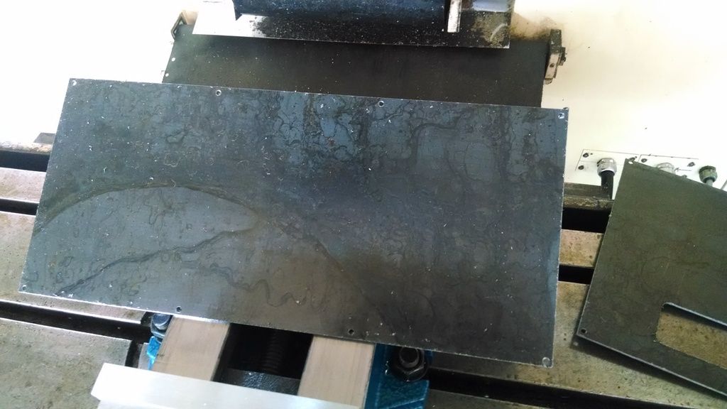
I fabricated a plate that will bolt on in place of the monitor panel on the operators panel. It has the perimeter bolt holes, the 75mm vesa mount bolt hole pattern and an access port for the cables to pass through for the touch screen monitor that will be mounted to the plate.
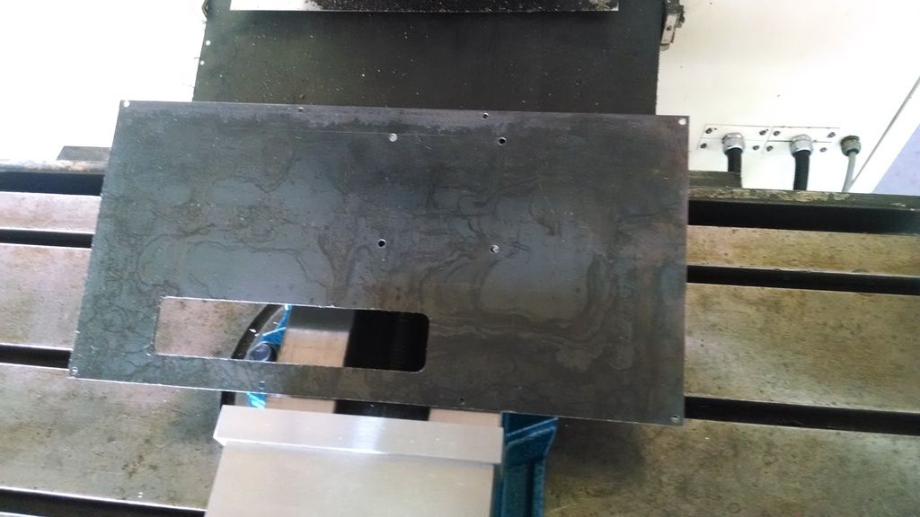
The second plate goes below the first plate and will replace the button panel and the estop button. I will cut a hole for the estop button but I have not yet. This panel will be later modified to add additional buttons as I see necessary at a later date. Maybe a pokeys button panel I am not sure yet. Currently this panel just has the perimeter mounting holes. I still need to sand prime and paint both of these panels.
Next I made a heat sink mount for the rectifier bridge that I will utilize on the 168V 2KVA DC power supply for the servo drives. This heat sink mount will attach to the transformer case that will be used in the power supply. The rectifier bridge bolts to the top hole on the heat sink. The other two holes allow the heat sink to be mounted to the transformer case.
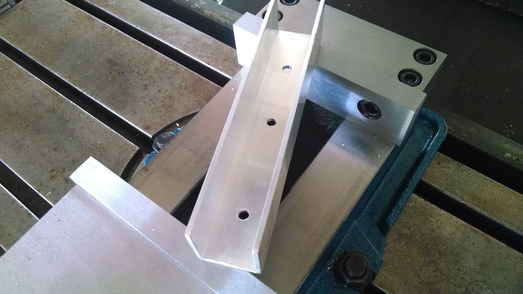
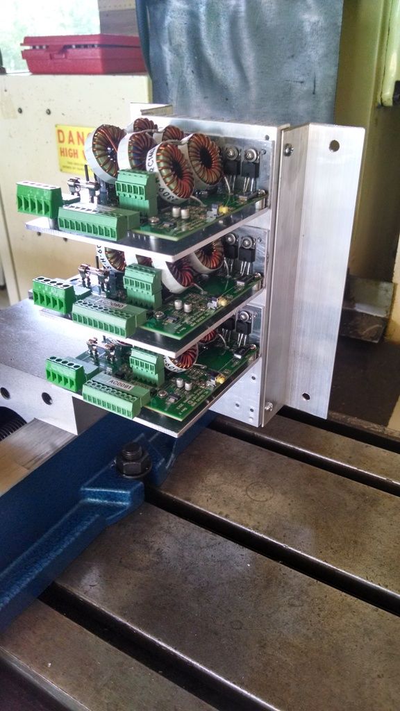
Next I made mounting brackets for the servo drive heat sink. Jon Elson provided the heat sink. He sent the heat sink and three servo drives already assembled with thermal paste between the drive brackets and the heat sink. Sadly I had to disassemble the unit to make my mounting brackets. I should have had him drill the mounting holes that I wanted while he was making the heat sink. Then I would not have had to disassemble the unit. Anyway, I drilled two holes on both sides of the heat sink. I then drilled matching holes in 1-1/2" x 1-1/2" x 1/16" aluminum angle. The aluminum angle will then be bolted to the back insert plate in the power cabinet. The two VFD's will also be mounted to the back insert plate. I will post an initial cad rendering of the power cabinet later tonight.
Besides the PC that is the progress that I have made so far.
I fabricated a plate that will bolt on in place of the monitor panel on the operators panel. It has the perimeter bolt holes, the 75mm vesa mount bolt hole pattern and an access port for the cables to pass through for the touch screen monitor that will be mounted to the plate.
The second plate goes below the first plate and will replace the button panel and the estop button. I will cut a hole for the estop button but I have not yet. This panel will be later modified to add additional buttons as I see necessary at a later date. Maybe a pokeys button panel I am not sure yet. Currently this panel just has the perimeter mounting holes. I still need to sand prime and paint both of these panels.
Next I made a heat sink mount for the rectifier bridge that I will utilize on the 168V 2KVA DC power supply for the servo drives. This heat sink mount will attach to the transformer case that will be used in the power supply. The rectifier bridge bolts to the top hole on the heat sink. The other two holes allow the heat sink to be mounted to the transformer case.
Next I made mounting brackets for the servo drive heat sink. Jon Elson provided the heat sink. He sent the heat sink and three servo drives already assembled with thermal paste between the drive brackets and the heat sink. Sadly I had to disassemble the unit to make my mounting brackets. I should have had him drill the mounting holes that I wanted while he was making the heat sink. Then I would not have had to disassemble the unit. Anyway, I drilled two holes on both sides of the heat sink. I then drilled matching holes in 1-1/2" x 1-1/2" x 1/16" aluminum angle. The aluminum angle will then be bolted to the back insert plate in the power cabinet. The two VFD's will also be mounted to the back insert plate. I will post an initial cad rendering of the power cabinet later tonight.
Besides the PC that is the progress that I have made so far.
Please Log in or Create an account to join the conversation.
- LearningLinuxCNC
-
Topic Author
- Offline
- Elite Member
-
Less
More
- Posts: 319
- Thank you received: 48
18 May 2015 11:52 #58812
by LearningLinuxCNC
Replied by LearningLinuxCNC on topic RB1-CNC Retrofit
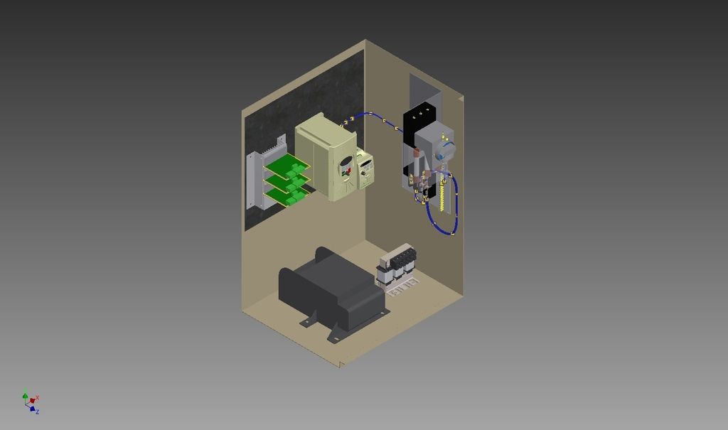
Here is a preliminary screenshot of the power cabinet arrangement. It has the servo drives on the left. The spindle VFD in the middle. The coolant VFD on the right. There is the main power disconnect on the far upper right. There is a power distribution panel just below it on the right side.
On the floor there is the 2KVA transformer for the servo drives and a placeholder for a line reactor for the spindle VFD if needed. I am preserving the spacing required for the VFD's and I think everything will be accessible without trouble. I will finish wiring the cabinet in CAD to make sure I won't have any issues.
On the floor there is the 2KVA transformer for the servo drives and a placeholder for a line reactor for the spindle VFD if needed. I am preserving the spacing required for the VFD's and I think everything will be accessible without trouble. I will finish wiring the cabinet in CAD to make sure I won't have any issues.
Please Log in or Create an account to join the conversation.
- andypugh
-

- Offline
- Moderator
-

Less
More
- Posts: 23377
- Thank you received: 4966
18 May 2015 20:38 #58820
by andypugh
Replied by andypugh on topic RB1-CNC Retrofit
You might not need a coolant VFD. The coolant pump on my mill runs perfectly adequately with only the addition of a capacitor.
Please Log in or Create an account to join the conversation.
- LearningLinuxCNC
-
Topic Author
- Offline
- Elite Member
-
Less
More
- Posts: 319
- Thank you received: 48
19 May 2015 09:55 #58849
by LearningLinuxCNC
Replied by LearningLinuxCNC on topic RB1-CNC Retrofit
Andy,
Good call on the run capacitor for the coolant pump. I did not think of that. However I already have the VFDs in hand for both the spindle and the coolant pump. Since I already have them I will proceed that way.
Good call on the run capacitor for the coolant pump. I did not think of that. However I already have the VFDs in hand for both the spindle and the coolant pump. Since I already have them I will proceed that way.
Please Log in or Create an account to join the conversation.
- LearningLinuxCNC
-
Topic Author
- Offline
- Elite Member
-
Less
More
- Posts: 319
- Thank you received: 48
20 May 2015 10:13 #58882
by LearningLinuxCNC
Replied by LearningLinuxCNC on topic RB1-CNC Retrofit
Progress update.
Last night I painted the panels for the operator panel. I took a vacation day today. Had family stuff to do this morning. This afternoon I worked on the retrofit. I finished up the power distribution panel. I then worked on machining a circuit board for the 168V DC power supply for the servo motors.
This was the first time that I have machined a circuit board on my CNC router. I used a .03125" ball end mill. This was also the first time that I used Inventor HSM as my cam software. I will say that it was pretty easy and intuitive to set up the CAM. The post processor worked OK. I found a couple things in the G code that I needed to fix. They all involved G28 commands. I simply removed the G28's as they weren't needed anyway. 4 test runs on the spoilboard later the code was ready to run on the copper circuit board.
Here is a picture of all of the progress.
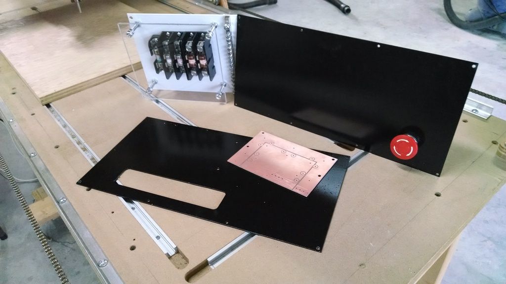
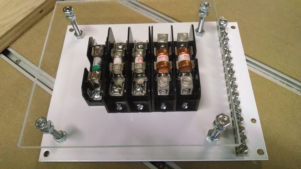
Here is a closeup of the power distribution board. There are fuses for the spindle VFD, coolant pump VFD, and the 120V line I will run to the computer cabinet to power the PC and monitor. I also have a grounding strip where I will land all of the grounds in the cabinet. I put an acrylic cover plate over the fuses so that when I am in the cabinet working with the VFDs while the power is on I will be protected.
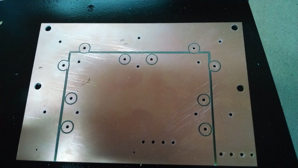
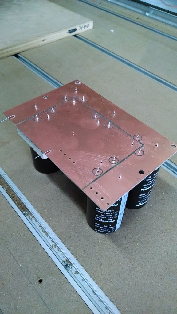
Here is a closeup of the circuit board after I completed milling and drilling the holes in it. I just spot drilled the holes on the router then I manually drilled the holes to size since I did not have the special drill bits for my router. This circuit board is for putting (5) 3300uf smoothing capacitors on the dc side of the power supply. There is also a 5K 10W resistor for draining the caps after power down.
Here is one with the components temporarily mounted to make sure everything was good.
I have a video of the router cutting the circuit board that I am uploading to youtube now. I will add it in a reply below tomorrow morning.
I should start removing the existing components from the machine this weekend. It is a long weekend so I hope to get quite a bit completed.
Last night I painted the panels for the operator panel. I took a vacation day today. Had family stuff to do this morning. This afternoon I worked on the retrofit. I finished up the power distribution panel. I then worked on machining a circuit board for the 168V DC power supply for the servo motors.
This was the first time that I have machined a circuit board on my CNC router. I used a .03125" ball end mill. This was also the first time that I used Inventor HSM as my cam software. I will say that it was pretty easy and intuitive to set up the CAM. The post processor worked OK. I found a couple things in the G code that I needed to fix. They all involved G28 commands. I simply removed the G28's as they weren't needed anyway. 4 test runs on the spoilboard later the code was ready to run on the copper circuit board.
Here is a picture of all of the progress.
Here is a closeup of the power distribution board. There are fuses for the spindle VFD, coolant pump VFD, and the 120V line I will run to the computer cabinet to power the PC and monitor. I also have a grounding strip where I will land all of the grounds in the cabinet. I put an acrylic cover plate over the fuses so that when I am in the cabinet working with the VFDs while the power is on I will be protected.
Here is a closeup of the circuit board after I completed milling and drilling the holes in it. I just spot drilled the holes on the router then I manually drilled the holes to size since I did not have the special drill bits for my router. This circuit board is for putting (5) 3300uf smoothing capacitors on the dc side of the power supply. There is also a 5K 10W resistor for draining the caps after power down.
Here is one with the components temporarily mounted to make sure everything was good.
I have a video of the router cutting the circuit board that I am uploading to youtube now. I will add it in a reply below tomorrow morning.
I should start removing the existing components from the machine this weekend. It is a long weekend so I hope to get quite a bit completed.
Please Log in or Create an account to join the conversation.
- LearningLinuxCNC
-
Topic Author
- Offline
- Elite Member
-
Less
More
- Posts: 319
- Thank you received: 48
20 May 2015 19:16 - 20 May 2015 19:18 #58890
by LearningLinuxCNC
Replied by LearningLinuxCNC on topic RB1-CNC Retrofit
Here is the video of cutting the circuit board.
Last edit: 20 May 2015 19:18 by LearningLinuxCNC.
Please Log in or Create an account to join the conversation.
- LearningLinuxCNC
-
Topic Author
- Offline
- Elite Member
-
Less
More
- Posts: 319
- Thank you received: 48
24 May 2015 07:19 #58961
by LearningLinuxCNC
Replied by LearningLinuxCNC on topic RB1-CNC Retrofit
Well I have been working on the machine a little in the evenings this week. I finished up the DC power supply for the servo drives. I worked on some layout cad work last night. Found that I need to reorient the power supply to avoid the transformer that is mounted on the door of the power cabinet.
Then today I really let it rip. I started and completed the tear down of the Fanuc and Siemens controls. I removed all of the Fanuc controls including the operator panel. I removed the cables that I will not use in the retrofit.
I removed the Siemens Simodrive servo controller. I cleaned out the cabinets relabeled all of the cables. Mounted the power distribution panel.
I installed the control panel plates that I previously fabricated. I installed the touch screen on the operator panel. I ran the USB cable and HDMI cables from the control cabinet to the operator panel.
Tomorrows tasks are to fabricate the mounting panels for the VFDs and servo drives in the power cabinet. Fabricate the mounting panel for the Pico UPS board and the PC motherboard, hard drive and power supply. If I have time I will fabricate the panels where I will mount the honda connectors to interface with the existing cables. Oh I also need to make standoffs to mount the boards to the mounting panels. Gotta love using your tools to work on your tools! So much fun.
Hope to have much progress to show tomorrow.
I don't have any pictures for today but I will try to post some tomorrow.
Please Log in or Create an account to join the conversation.
- LearningLinuxCNC
-
Topic Author
- Offline
- Elite Member
-
Less
More
- Posts: 319
- Thank you received: 48
26 May 2015 09:30 #59056
by LearningLinuxCNC
Replied by LearningLinuxCNC on topic RB1-CNC Retrofit
Another update with some pictures this time.
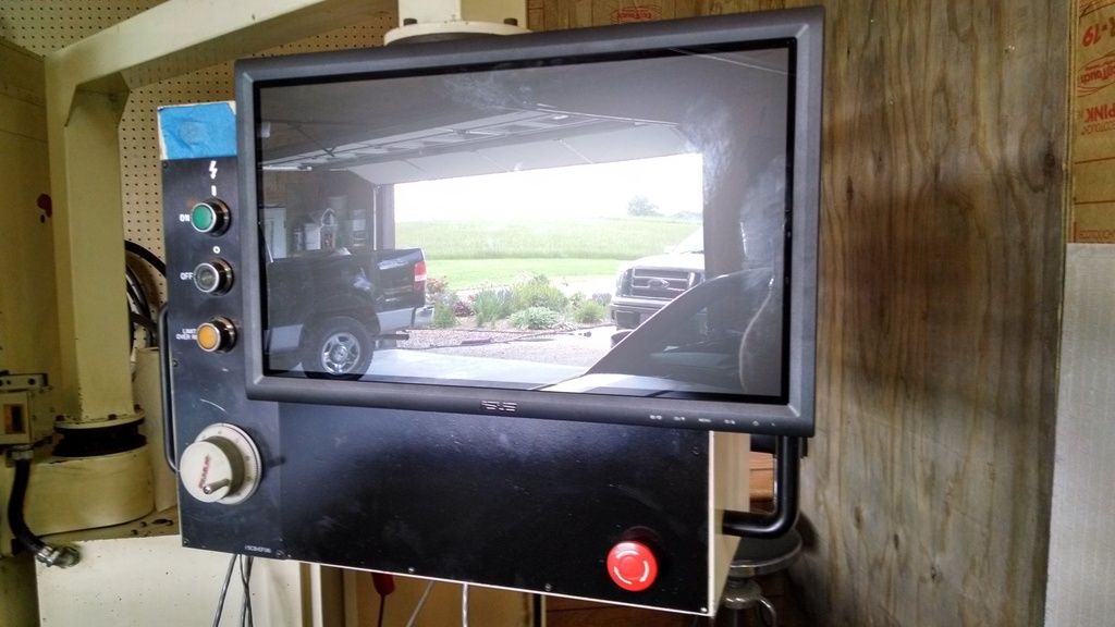
Here is a picture of the user control panel with the touch screen monitor mounted.
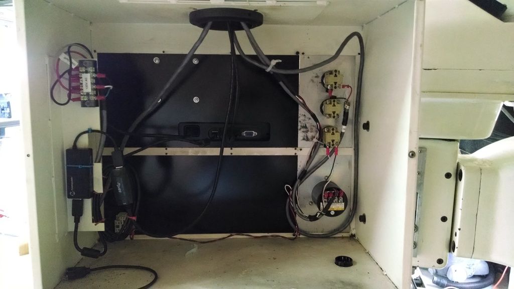
Here is a picture of the inside of the user control panel. I have a USB 3.0 hub installed in the panel to connect the touch screen interface and for a remote port for using a USB flash drive. I have not mounted the panel mount USB port on the front of the panel yet.
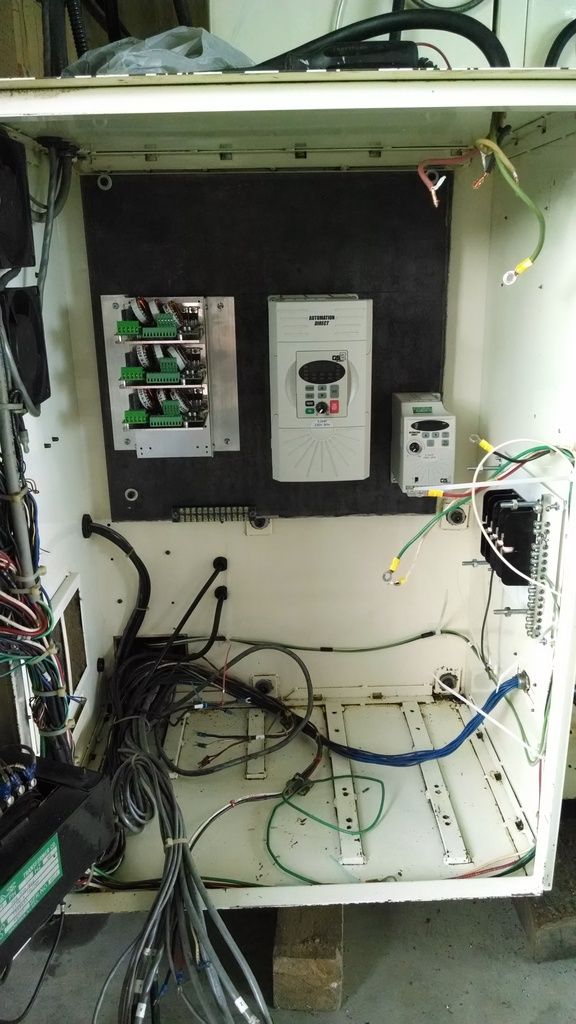
I have the VFDs and the servo drives mounted in the power cabinet.
I also have the 120VAC power ran from the main distribution fuse block to the computer cabinet to the user control panel.
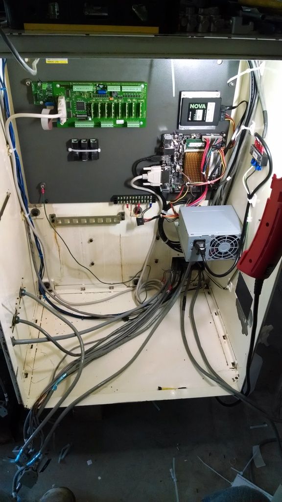
I have the majority of the PC and interface components mounted in the computer cabinet.
I still need to make the adapters to go from the Honda connectors to RJ45 connectors for the encoder differential signal receivers.
I have made good progress but there is still lots to do.
Here is a picture of the user control panel with the touch screen monitor mounted.
Here is a picture of the inside of the user control panel. I have a USB 3.0 hub installed in the panel to connect the touch screen interface and for a remote port for using a USB flash drive. I have not mounted the panel mount USB port on the front of the panel yet.
I have the VFDs and the servo drives mounted in the power cabinet.
I also have the 120VAC power ran from the main distribution fuse block to the computer cabinet to the user control panel.
I have the majority of the PC and interface components mounted in the computer cabinet.
I still need to make the adapters to go from the Honda connectors to RJ45 connectors for the encoder differential signal receivers.
I have made good progress but there is still lots to do.
Please Log in or Create an account to join the conversation.
Time to create page: 0.090 seconds