RB1-CNC Retrofit
- LearningLinuxCNC
-
 Topic Author
- Offline
- Elite Member
-

Less
More
- Posts: 319
- Thank you received: 48
04 Jun 2015 18:51 #59427
by LearningLinuxCNC
Replied by LearningLinuxCNC on topic RB1-CNC Retrofit
Here is the third HAL file univpwm_io.hal
# HAL config file for Pico Systems UPC board with threading
#
# Connect motion controller I/Os
#

# connect limit/home switch outputs to motion controller
#newsig Xminlim bit
#newsig Xmaxlim  bit
newsig Xhome bit
#net Xminlim <= ppmc.0.din.01.in
#net Xminlim => axis.0.neg-lim-sw-in
#net Xmaxlim <= ppmc.0.din.02.in
#net Xmaxlim => axis.0.pos-lim-sw-in
net Xhome <= ppmc.0.din.04.in
net Xhome => axis.0.home-sw-in

#newsig Yminlim bit
#newsig Ymaxlim  bit
newsig Yhome bit
#net Yminlim <= ppmc.0.din.05.in
#net Yminlim => axis.1.neg-lim-sw-in
#net Ymaxlim <= ppmc.0.din.06.in
#net Ymaxlim => axis.1.pos-lim-sw-in
net Yhome <= ppmc.0.din.05.in
net Yhome => axis.1.home-sw-in

#newsig Zminlim bit
#newsig Zmaxlim  bit
newsig Zhome bit
#net Zminlim <= ppmc.0.din.09.in
#net Zminlim => axis.2.neg-lim-sw-in
#net Zmaxlim <= ppmc.0.din.10.in
#net Zmaxlim => axis.2.pos-lim-sw-in
net Zhome <= ppmc.0.din.06.in
net Zhome => axis.2.home-sw-in

#newsig Aminlim bit
#newsig Amaxlim  bit
#newsig Ahome bit
#net Aminlim <= ppmc.0.din.12.in
#net Aminlim => axis.3.neg-lim-sw-in
#net Amaxlim <= ppmc.0.din.13.in
#net Amaxlim => axis.3.pos-lim-sw-in
#net Ahome <= ppmc.0.din.11.in
#net Ahome => axis.3.home-sw-in


# connect index pulses to motion controller
# do these when index pulsing is figured out
newsig Xindex bit
newsig Yindex  bit
newsig Zindex bit
net Xindex <= ppmc.0.encoder.00.index-enable
net Xindex => axis.0.index-enable
net Yindex <= ppmc.0.encoder.01.index-enable
net Yindex => axis.1.index-enable
net Zindex <= ppmc.0.encoder.02.index-enable
net Zindex => axis.2.index-enable

#
# Connect I/O controller I/Os
#

# connect e-stop write/sense to I/O controller
# and univpwm's fault with estop's output, so  estop FF is reset, but
#      prevent continued estop signal from univpwm from holding FF cleared
newsig ppmcEstop bit
net ppmcEstop ppmc.0.din.15.in-not
net ppmcEstop and2.0.in0
newsig EstopOkIn bit
net EstopOkIn estop-latch.0.fault-in
net EstopOkIn and2.0.out
newsig EstopOkOut bit
net EstopOkOut <= ppmc.0.dout.07.out
net EstopOkOut iocontrol.0.emc-enable-in
net EstopOkOut estop-latch.0.ok-out
net EstopOkOut and2.0.in1
newsig emc-estop-out bit
net emc-estop-out iocontrol.0.user-enable-out
net emc-estop-out estop-latch.0.ok-in
newsig emc-estop-reset bit
net emc-estop-reset iocontrol.0.user-request-enable
net emc-estop-reset estop-latch.0.reset

# connect spindle fwd/rev to I/O controller
newsig SpindleFwd bit
newsig SpindleRev bit
net SpindleFwd <= ppmc.0.dout.00.out
net SpindleFwd => motion.spindle-forward
net SpindleRev <= ppmc.0.dout.01.out
net SpindleRev => motion.spindle-reverse

# connect spindle speed up/down to I/O controller
#newsig SpindleUp bit
#newsig SpindleDown bit
#net SpindleUp <= ppmc.0.dout.06.out
#net SpindleUp => motion.spindle-incr-speed
#net SpindleDown <= ppmc.0.dout.05.out
#net SpindleDown => motion.spindle-decr-speed

# connect spindle brake to I/O controller
newsig SpindleBrakeOn bit
net SpindleBrakeOn <= ppmc.0.dout.06.out
net SpindleBrakeOn => motion.spindle-brake

# connect mist/flood coolant to I/O controller
#newsig MistOn bit
newsig FloodOn bit
#net MistOn <= ppmc.0.dout.02.out
#net MistOn => iocontrol.0.coolant-mist
net FloodOn <= ppmc.0.dout.03.out
net FloodOn => iocontrol.0.coolant-flood

# connect high gear selector switch to I/O controller
newsig HighGear bit
net HighGear <= ppmc.0.din.00.in

# connect spindle running input to I/O controller
newsig SpindleRunning bit
net SpindleRunning <= ppmc.0.din.01.in

# connect coolant running input to I/O controller
newsig CoolantRunning bit
net CoolantRunning <= ppmc.0.din.02.in

# connect LowLube switch to I/O controller
newsig LowLube bit
net LowLube <= ppmc.0.din.03.in
Please Log in or Create an account to join the conversation.
- andypugh
-

- Offline
- Moderator
-

Less
More
- Posts: 23383
- Thank you received: 4968
04 Jun 2015 18:57 #59428
by andypugh
The problem is that you can't get off the limit switches if they drive e-stop as the software limit-override (that the GUIs support) won't work.
The physical bypass button means that this isn't such a serious problem, though the user might wonder why the software limits-override doesn't work.
Replied by andypugh on topic RB1-CNC Retrofit
What other problems do you foresee with this configuration?
The problem is that you can't get off the limit switches if they drive e-stop as the software limit-override (that the GUIs support) won't work.
The physical bypass button means that this isn't such a serious problem, though the user might wonder why the software limits-override doesn't work.
Please Log in or Create an account to join the conversation.
- LearningLinuxCNC
-
Topic Author
- Offline
- Elite Member
-
Less
More
- Posts: 319
- Thank you received: 48
04 Jun 2015 18:59 #59429
by LearningLinuxCNC
Replied by LearningLinuxCNC on topic RB1-CNC Retrofit
And the fourth and final HAL file univpwm_motion.hal
I think I have the jist of what is going on in the HAL files but let me know if you see something suspect. I may be overlooking something. Keep in mind I have the same issue with the watchdog and e-stop with the sampe UPC configuration (Unmodified HAL files).
# HAL config file for Pico Systems UPC board using Velocity Estimation
#

# set the PWM frequency to suit Pico's PWM amps (50KHz)
# users with other amps may need to change this
setp ppmc.0.pwm.00-03.freq 50000
# turn on bootstrapping for the MOSFET drivers
# this also depends on the amplifiers
setp ppmc.0.pwm.00.bootstrap TRUE
setp ppmc.0.pwm.01.bootstrap TRUE
setp ppmc.0.pwm.02.bootstrap TRUE
#setp ppmc.0.pwm.03.bootstrap TRUE
# set max duty cycle to 95% for the MOSFET drives
# at 50KHz this corresponds to 1 us
setp ppmc.0.pwm.00.max-dc 0.95
setp ppmc.0.pwm.01.max-dc 0.95
setp ppmc.0.pwm.02.max-dc 0.95
#setp ppmc.0.pwm.03.max-dc 0.95

setp ppmc.0.encoder.00.min-speed-estimate 0.001
setp ppmc.0.encoder.01.min-speed-estimate 0.001
setp ppmc.0.encoder.02.min-speed-estimate 0.001
#setp ppmc.0.encoder.03.min-speed-estimate 0.001

# Here's the part that connects the encoder velocity to the PID
net Xfbderiv ppmc.0.encoder.00.velocity pid.0.feedback-deriv
net Yfbderiv ppmc.0.encoder.01.velocity pid.1.feedback-deriv
net Zfbderiv ppmc.0.encoder.02.velocity pid.2.feedback-deriv

# connect position feedback signals to encoders
net Xpos-fb <= ppmc.0.encoder.00.position
net Ypos-fb <= ppmc.0.encoder.01.position
net Zpos-fb <= ppmc.0.encoder.02.position
#net Apos-fb <= ppmc.0.encoder.03.position

# get feedback scaling from ini file
setp ppmc.0.encoder.00.scale [AXIS_0]INPUT_SCALE
setp ppmc.0.encoder.01.scale [AXIS_1]INPUT_SCALE
setp ppmc.0.encoder.02.scale [AXIS_2]INPUT_SCALE
#setp ppmc.0.encoder.03.scale 6912

# connect PID output signals to PWM generators
net Xoutput => ppmc.0.pwm.00.value
net Youtput => ppmc.0.pwm.01.value
net Zoutput => ppmc.0.pwm.02.value

# connect axis enables to PWM generators
net Xenable => ppmc.0.pwm.00.enable
net Yenable => ppmc.0.pwm.01.enable
net Zenable => ppmc.0.pwm.02.enable

# set output scaling from ini file
setp ppmc.0.pwm.00.scale [AXIS_0]OUTPUT_SCALE
setp ppmc.0.pwm.01.scale [AXIS_1]OUTPUT_SCALE
setp ppmc.0.pwm.02.scale [AXIS_2]OUTPUT_SCALE

# add a couple of tuning test links
# if these are useful will want to add them to the other axes as well
# or make these setup with the tuning script
net Xoutput ddt.0.in
net Xpos-fb ddt.1.in

newsig spindle-sync bit
newsig spindle-index-en bit
net spindle-index-en => ppmc.0.encoder.03.index-enable

# hook up motion controller's sync output
net spindle-index-en <= motion.spindle-index-enable

# report rev count to motion controller
newsig spindle-pos float
net spindle-pos <= ppmc.0.encoder.03.position
net spindle-pos => motion.spindle-revs

# set up 4th PWM generator as a spindle speed control
newsig spindle-speed float
newsig spindle-pwm-cmd float
newsig spindle-pwm-filt float
net spindle-speed <= motion.spindle-speed-out
net spindle-speed => mult2.1.in0
setp mult2.1.in1 0.0009018
net spindle-pwm-cmd <= mult2.1.out
net spindle-pwm-cmd => lowpass.0.in
net spindle-pwm-filt <= lowpass.0.out
net spindle-pwm-filt => ppmc.0.pwm.03.value
setp lowpass.0.gain 0.005

newsig spindle-enable bit
# SpindleFwd and SpindleRev come from univpwm_io.hal
net SpindleFwd => or2.0.in0
net SpindleRev => or2.0.in1
net spindle-enable <= or2.0.out
net spindle-enable => ppmc.0.pwm.03.enable
# spindle speed display
net spinraw    ppmc.0.encoder.03.delta conv-s32-float.0.in
net spinfloat  conv-s32-float.0.out mult2.0.in0
setp mult2.0.in1 8.6805555
newsig SpindleRPM float
net SpindleRPM <= mult2.0.out
I think I have the jist of what is going on in the HAL files but let me know if you see something suspect. I may be overlooking something. Keep in mind I have the same issue with the watchdog and e-stop with the sampe UPC configuration (Unmodified HAL files).
Please Log in or Create an account to join the conversation.
- LearningLinuxCNC
-
Topic Author
- Offline
- Elite Member
-
Less
More
- Posts: 319
- Thank you received: 48
06 Jun 2015 18:56 #59515
by LearningLinuxCNC
Replied by LearningLinuxCNC on topic RB1-CNC Retrofit
I took the Pico UPC card to Jon Elson so he could diagnose if there was a problem with my card. The testing showed that there was an issue with the firmware on the card. Jon is working on a new revision of the firmware that will correct the watchdog issue. Apparently no one is using the watchdog on the latest firmware as this problem would have showed up before now. There should be a fix to the problem soon.
Also Jon does test each card before it is shipped to make sure everything works. Unfortunately the test protocol did not look at the live watchdog signal just the fact that the watchdog will kill the e-stop circuit. Jon is also going to update the test protocol to check for the live watchdog signal.
I spent the evening finishing most of the wiring. I still have to make my break out board for the hall sensors cables so i can connect them to the servo drives. Then it will be time to power the beast up. Hopefully I can get it powered up today and start servo tuning.
Please Log in or Create an account to join the conversation.
- LearningLinuxCNC
-
Topic Author
- Offline
- Elite Member
-
Less
More
- Posts: 319
- Thank you received: 48
07 Jun 2015 08:27 - 07 Jun 2015 08:31 #59554
by LearningLinuxCNC
Replied by LearningLinuxCNC on topic RB1-CNC Retrofit
Another photo update.
I finished wiring the servo drives and all of the other outputs. I should be done with the wiring for now. I still need to hook up the MPG encoder but I need to make an adapter board so that I can use the regular inputs on the UPC board. I am reserving the fourth encoder input for use on the spindle.
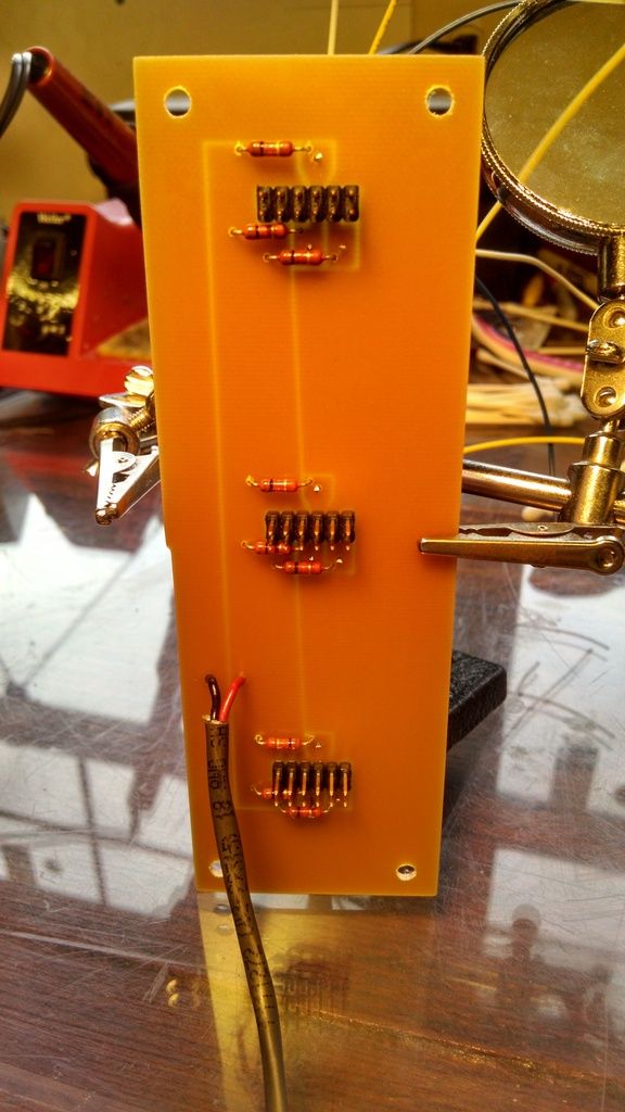
Here is a picture of the break out board for the hall sensors in the servo motors. The resistors are pull up resistors for the signals.
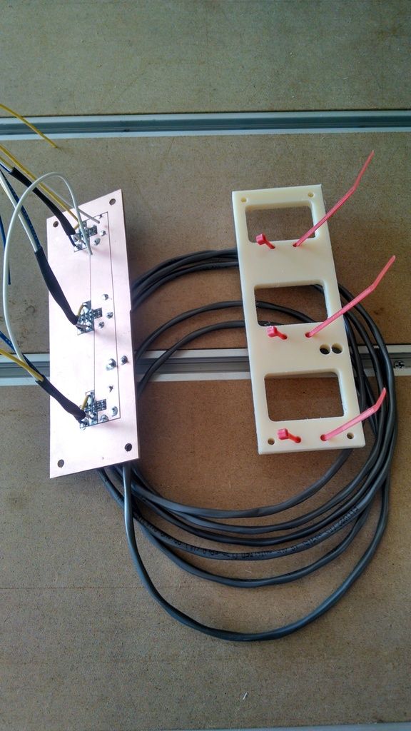
Here is the mounting bracket and the break out board. The mounting bracket bolts to the break out board and then it zip ties to the standoff posts on the servo drives.
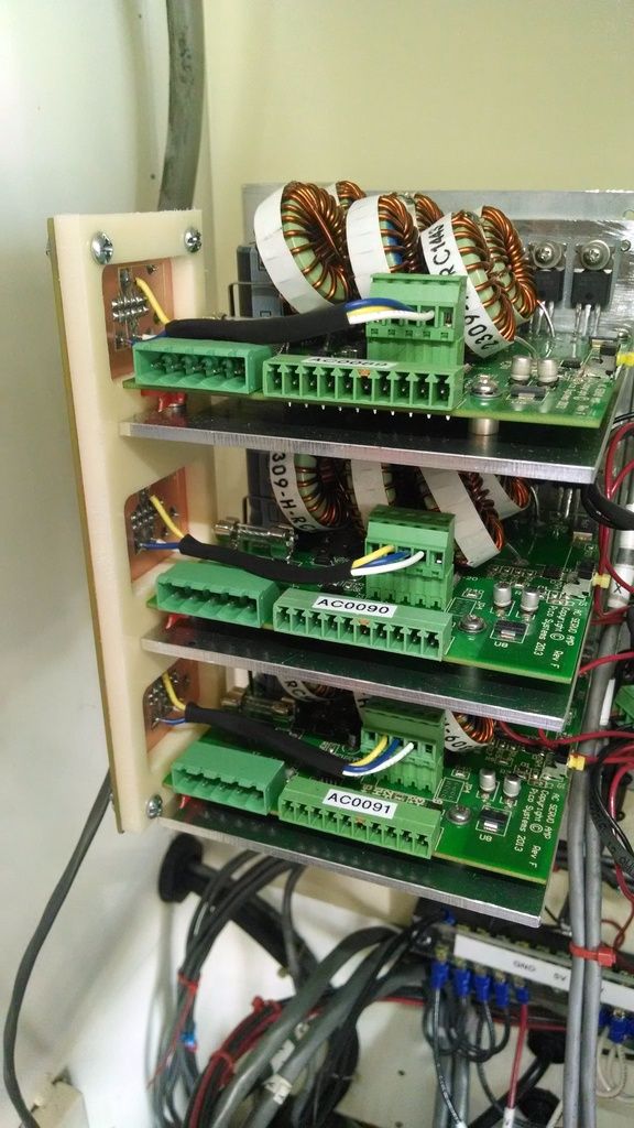
Here is the break out board and bracket mounted on the servo drives.
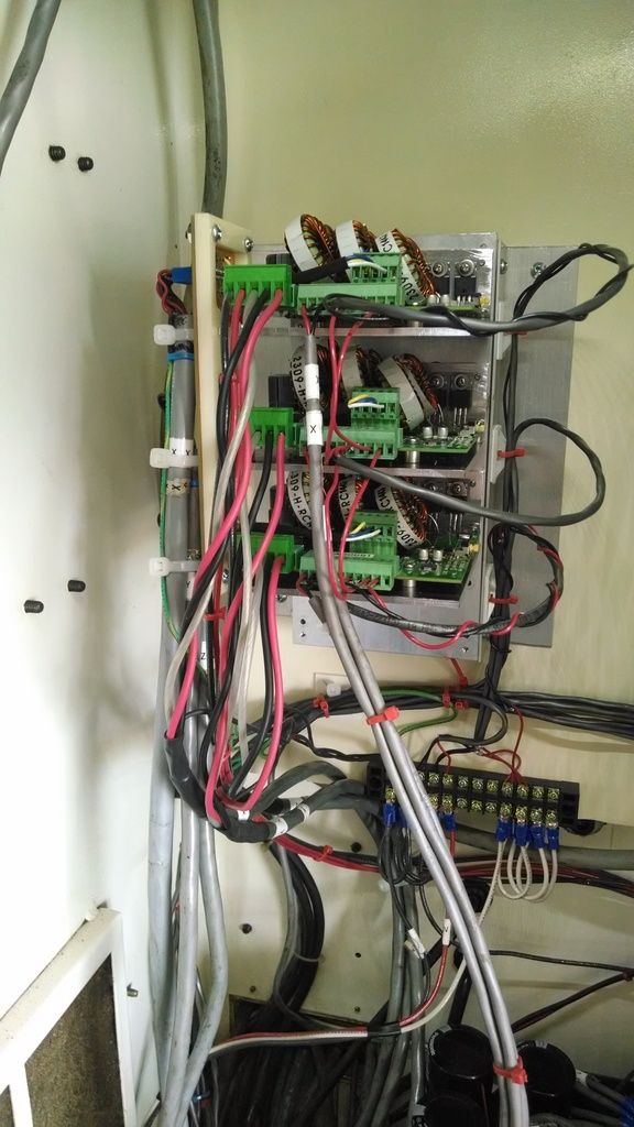
Here it is with all of the wiring. It is as organized as I can get it.
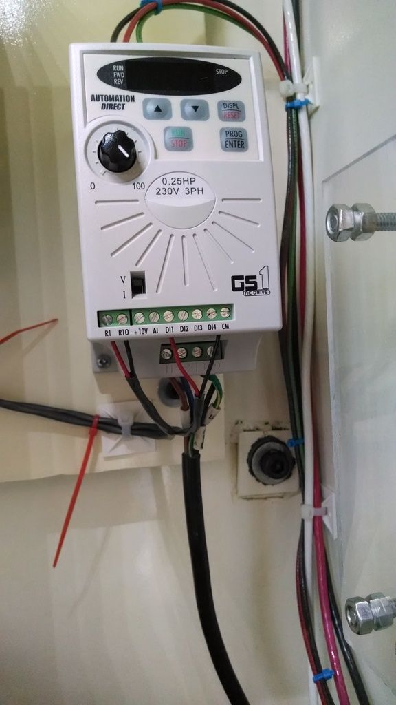
Wiring to the spindle VFD
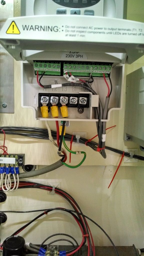
Wiring to the coolant pump VFD
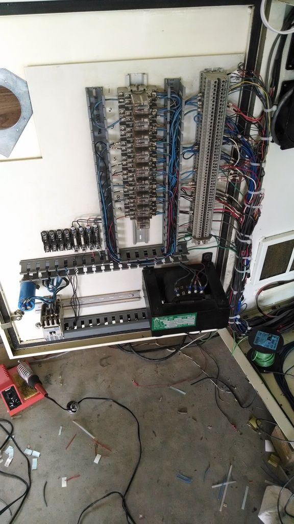
Here are all of the 24V control relays. Not all are required anymore but they are still there. The contactor at the bottom left is for turning on the power to the servos when the e-stop condition is released. The transformer on the lower right corner of the door provides isolated 115V for some controls and 20VAC for 24VDC. The rectifier bridge and smoothing cap are located above the contactor in the lower left corner.You can also see the scraps from my wiring madness on the floor below the door (labels, wire, zip ties, soldering iron).
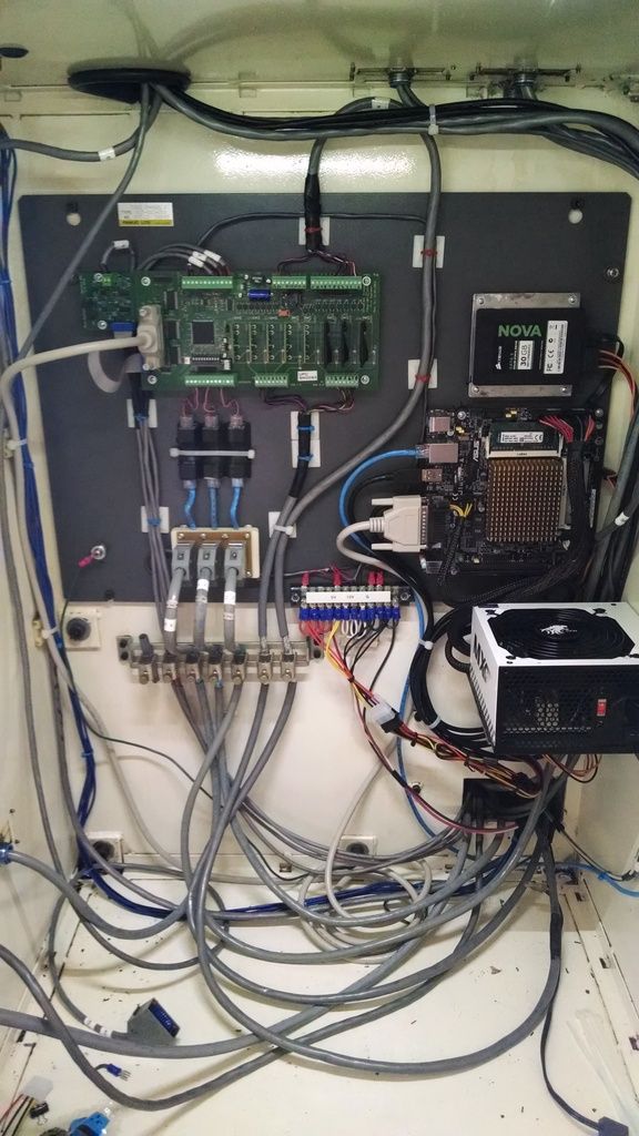
Here is a shot of the finished wiring in the computer cabinet side. The inputs are wired, the outputs are wired, the encoders are connected and the pwm signals are all connected to the UPC board. Also the spindle control wire is connected to the spindle control board in the upper left corner. 12V and 5V is supplied to the system from the pc ATX power supply. It is connected to the terminal strip at the bottom of the panel for distribution.
I did not get to start it up today as I had to work on cleaning out my workshop as the concrete floor is getting poured this next week. Getting a new home made for the machine.
I finished wiring the servo drives and all of the other outputs. I should be done with the wiring for now. I still need to hook up the MPG encoder but I need to make an adapter board so that I can use the regular inputs on the UPC board. I am reserving the fourth encoder input for use on the spindle.
Here is a picture of the break out board for the hall sensors in the servo motors. The resistors are pull up resistors for the signals.
Here is the mounting bracket and the break out board. The mounting bracket bolts to the break out board and then it zip ties to the standoff posts on the servo drives.
Here is the break out board and bracket mounted on the servo drives.
Here it is with all of the wiring. It is as organized as I can get it.
Wiring to the spindle VFD
Wiring to the coolant pump VFD
Here are all of the 24V control relays. Not all are required anymore but they are still there. The contactor at the bottom left is for turning on the power to the servos when the e-stop condition is released. The transformer on the lower right corner of the door provides isolated 115V for some controls and 20VAC for 24VDC. The rectifier bridge and smoothing cap are located above the contactor in the lower left corner.You can also see the scraps from my wiring madness on the floor below the door (labels, wire, zip ties, soldering iron).
Here is a shot of the finished wiring in the computer cabinet side. The inputs are wired, the outputs are wired, the encoders are connected and the pwm signals are all connected to the UPC board. Also the spindle control wire is connected to the spindle control board in the upper left corner. 12V and 5V is supplied to the system from the pc ATX power supply. It is connected to the terminal strip at the bottom of the panel for distribution.
I did not get to start it up today as I had to work on cleaning out my workshop as the concrete floor is getting poured this next week. Getting a new home made for the machine.
Last edit: 07 Jun 2015 08:31 by LearningLinuxCNC.
Please Log in or Create an account to join the conversation.
- LearningLinuxCNC
-
Topic Author
- Offline
- Elite Member
-
Less
More
- Posts: 319
- Thank you received: 48
08 Jun 2015 06:17 #59610
by LearningLinuxCNC
Replied by LearningLinuxCNC on topic RB1-CNC Retrofit
Today I cleaned up my mess from wiring and started testing the machine. I did not make it very far and i blew the fuses that supply power to the 160V DC power supply. The fuses that were installed were fast acting fuses and they blew on the inrush of powering up the power supply. I will have to order a different fuse holder and fuses to use time delay fuses to protect from short circuit but allow the inrush of starting the power supply.
Hopefully I will get it going on Tuesday.
Hopefully I will get it going on Tuesday.
Please Log in or Create an account to join the conversation.
- andypugh
-
- Offline
- Moderator
-
Less
More
- Posts: 23383
- Thank you received: 4968
08 Jun 2015 06:51 #59611
by andypugh
You could consider taking active control of your PSU.
The PSU I built for my machine has a 555-timer circuit which passes the current through a limiting resistor for a fixed time.
When the power goes off a relay drops out and shorts the caps out through a second resistor.
I have a timer in HAL which prevents me trying to turn the machine back on while the discharge relay is running (otherwise it arcs, welds, and acts as a short across the mains, which eventually ejects the resistor terminals through the PSU case....)
However, that isn't how I would do it if I was starting from scratch. My motor drives report back bus voltage to LinuxCNC. If I had realised that then I could have controlled the PSU from HAL.
1) When bus voltage reaches 300V close the relay that bypasses the input current limit resistor and report power-good to the system
2) When the machine turns off, inhibit turning it back on again until bus-voltage < 20 V.
All pretty simple in HAL, and much more "visible" than components in the PSU. HAL can control anything, not just compicated CNC machines.
This might be less easy if your drives don't report bus voltage on the HAL interface, but even then why build a timer circuit in the PSU when you can just take wires from a relay to your controller?
Replied by andypugh on topic RB1-CNC Retrofit
The fuses that were installed were fast acting fuses and they blew on the inrush of powering up the power supply. I will have to order a different fuse holder and fuses to use time delay fuses to protect from short circuit but allow the inrush of starting the power supply.
You could consider taking active control of your PSU.
The PSU I built for my machine has a 555-timer circuit which passes the current through a limiting resistor for a fixed time.
When the power goes off a relay drops out and shorts the caps out through a second resistor.
I have a timer in HAL which prevents me trying to turn the machine back on while the discharge relay is running (otherwise it arcs, welds, and acts as a short across the mains, which eventually ejects the resistor terminals through the PSU case....)
However, that isn't how I would do it if I was starting from scratch. My motor drives report back bus voltage to LinuxCNC. If I had realised that then I could have controlled the PSU from HAL.
1) When bus voltage reaches 300V close the relay that bypasses the input current limit resistor and report power-good to the system
2) When the machine turns off, inhibit turning it back on again until bus-voltage < 20 V.
All pretty simple in HAL, and much more "visible" than components in the PSU. HAL can control anything, not just compicated CNC machines.
This might be less easy if your drives don't report bus voltage on the HAL interface, but even then why build a timer circuit in the PSU when you can just take wires from a relay to your controller?
The following user(s) said Thank You: LearningLinuxCNC
Please Log in or Create an account to join the conversation.
- LearningLinuxCNC
-
Topic Author
- Offline
- Elite Member
-
Less
More
- Posts: 319
- Thank you received: 48
08 Jun 2015 07:27 - 08 Jun 2015 07:29 #59612
by LearningLinuxCNC
Replied by LearningLinuxCNC on topic RB1-CNC Retrofit
Andy,
That is exactly what I am considering doing. I have a discharge resistor already permanently installed across the cap bank to discharge the cap bank after the power supply is disconnected from the mains.
Currently my power supply is switched on when the e-stop is released. Relay 8 on the UPC board energizes a relay switching 115V to energize the contactor that connects the mains to the power supply. I have some contactors left over from the retrofit process. I was considering using one of them to pass the power through a resistor for 1-2 seconds then switch to just mains power without the resistor. I was going to do this with HAL and another output on the UPC board.
I don't have access to the voltage on the DC power supply through the drives. I will just have to do it based on time.
Is the issue with the discharge resistor just because of the relay or will I have the same issue if I re-energize after an e-stop? I am using a 5K 10W resistor.
First I am going to try the time delay fuses. If they don't work then I will add the HAL timer, Contactor and Resistor.
Last edit: 08 Jun 2015 07:29 by LearningLinuxCNC.
Please Log in or Create an account to join the conversation.
- andypugh
-
- Offline
- Moderator
-
Less
More
- Posts: 23383
- Thank you received: 4968
08 Jun 2015 23:40 #59629
by andypugh
I decided that any resistor with a suitable discharge time would be too big.
I have 10,000 uF at 300V.
A 5k resistor would need to be 20W and would take 2 minutes to 24V
If I wanted to discharge in 10 seconds then it needs to be a 500 ohm resistor, and one rated at 250W.
So, I decided to use a relay to switch-in the discharge resistor only when the input power is turned off. But the problem there is that relays don't mind making at 300VDC, but they don't want to break 300V DC.
The resistor is 500 ohm, but is actually only a 25W one, as it only sees 10s of use every day or so.
Replied by andypugh on topic RB1-CNC Retrofit
Is the issue with the discharge resistor just because of the relay or will I have the same issue if I re-energize after an e-stop? I am using a 5K 10W resistor..
I decided that any resistor with a suitable discharge time would be too big.
I have 10,000 uF at 300V.
A 5k resistor would need to be 20W and would take 2 minutes to 24V
If I wanted to discharge in 10 seconds then it needs to be a 500 ohm resistor, and one rated at 250W.
So, I decided to use a relay to switch-in the discharge resistor only when the input power is turned off. But the problem there is that relays don't mind making at 300VDC, but they don't want to break 300V DC.
The resistor is 500 ohm, but is actually only a 25W one, as it only sees 10s of use every day or so.
Please Log in or Create an account to join the conversation.
- LearningLinuxCNC
-
Topic Author
- Offline
- Elite Member
-
Less
More
- Posts: 319
- Thank you received: 48
13 Jun 2015 21:38 #59783
by LearningLinuxCNC
Replied by LearningLinuxCNC on topic RB1-CNC Retrofit
I did some more testing this week. Some good results, some VERY BAD!
I received the updated eprom from Jon at Pico Systems. It corrected the issue with the watchdog. Now the watchdog properly stops the e-stop and allows the e-stop to work with the hardware swtiches and the software swtich in LinuxCNC. (Good)
I installed the new fuses on the power lines to the 160V dc power supply. I blew the first set as when I reconnected the power supply I connected the leads to the rectifier incorrectly which caused a short and blew the fuses (Bad). I found my error and installed the new fuses and the power supply worked (Good). I also had to replace the contactor that sends AC power to the 160V power supply as it was not switching reliably.
I Then tested the z-axis brake to make sure that it released the axis with e-stop off and held the axis with e-stop tripped. This also worked (Good). One note use some cribbing while doing this test to make sure the z-axis does not crash into the end stop of the axis causing physical damage. I used a floor jack with the lift pad about 1/2" below the spindle head to catch the head when it started to drop. This should not happen once the servo drive is enabled as the drive will hold the axis in place.
I then tested the outputs from LinuxCNC and the Pico UPC board. The spindle brake output works. When the spindle is stopped the spindle brake is enabled. When the spindle is turned on the brake is released. (Good)
I had an issue with the outputs controlling the vsd inputs for the spindle for fwd, stop and rev, stop. I was using the Pico SSRs on these outputs as the required current should be less than 15ma (the limit for the Pico SSRs). The Pico SSRs would not start the spindle in either the fwd or rev direction. (Bad) I then switched over the Crydom SSRs that I have for high current application and they were able to switch the fwd and rev directions on and off (Good). I later discussed with Jon at Pico and he said the Pico SSRs are not bi directional so he recommended to swap the leads to the outputs to see if that fixes the problem. I have not been able to try that configuration yet to see if it fixes the issue.
Now for the VERY BAD. . .
I was ready to try the X axis servo tuning. I made two changes to the machine configuration to start on the servo tuning. I tied the negative sides of the 160V DC power supply and the negative side of the ATX power supply together. The ATX power supply powers the computer, UPC board (12V), Servo drives (12V), servo motor hall sensors (5V), encoders (5V). I also connected power and the motor to the X-Axis servo drive. I powered the machine on. and cleared the e-stop. Then POP. My computer screen goes blank. (VERY BAD).
The pop did not blow any fuses. I wonder what happened. I removed the ATX power supply and put in a power supply out of another computer. The PC will not start up and starts smoking just with standby power from the power supply. Motherboard blown. I test the original ATX power supply in the machine it will not power up by tying the power on lead to ground. Power supply blown. (VERY BAD, VERY BAD, VERY BAD)
I power up the UPC board and it powers up fine and the e-stop circuit works fine. (Good)
What went wrong? I changed two things before the magic smoke came out. Connected the two power supply negatives together and connected power to the servo drive.
Turns out I made a VERY STUPID MISTAKE. I swapped the positive and negative from the 160V power supply on the X-axis servo drive. I am sure this fed 160V back through the ATX power supply toasting the supply and PC. Hopefully it did not damage the Hall sensors, encoders, ssd, memory, etc.
Moral of the story: ALWAYS CHECK AND DOUBLE CHECK AND TRIPLE CHECK YOUR CONNECTIONS TO MAKE SURE THEY ARE WIRED CORRECTLY. So far this is an expensive mistake that may be way more expensive if the encoders or hall sensors or servo drive are toast as well.
I am posting this as a learning experience for everyone doing changes to a machine. I made a very stupid mistake, don't do the same.
I have a new motherboard and power supply ordered so hopefully I will be back in business next weekend. I will be out of commission for a while now.
I received the updated eprom from Jon at Pico Systems. It corrected the issue with the watchdog. Now the watchdog properly stops the e-stop and allows the e-stop to work with the hardware swtiches and the software swtich in LinuxCNC. (Good)
I installed the new fuses on the power lines to the 160V dc power supply. I blew the first set as when I reconnected the power supply I connected the leads to the rectifier incorrectly which caused a short and blew the fuses (Bad). I found my error and installed the new fuses and the power supply worked (Good). I also had to replace the contactor that sends AC power to the 160V power supply as it was not switching reliably.
I Then tested the z-axis brake to make sure that it released the axis with e-stop off and held the axis with e-stop tripped. This also worked (Good). One note use some cribbing while doing this test to make sure the z-axis does not crash into the end stop of the axis causing physical damage. I used a floor jack with the lift pad about 1/2" below the spindle head to catch the head when it started to drop. This should not happen once the servo drive is enabled as the drive will hold the axis in place.
I then tested the outputs from LinuxCNC and the Pico UPC board. The spindle brake output works. When the spindle is stopped the spindle brake is enabled. When the spindle is turned on the brake is released. (Good)
I had an issue with the outputs controlling the vsd inputs for the spindle for fwd, stop and rev, stop. I was using the Pico SSRs on these outputs as the required current should be less than 15ma (the limit for the Pico SSRs). The Pico SSRs would not start the spindle in either the fwd or rev direction. (Bad) I then switched over the Crydom SSRs that I have for high current application and they were able to switch the fwd and rev directions on and off (Good). I later discussed with Jon at Pico and he said the Pico SSRs are not bi directional so he recommended to swap the leads to the outputs to see if that fixes the problem. I have not been able to try that configuration yet to see if it fixes the issue.
Now for the VERY BAD. . .
I was ready to try the X axis servo tuning. I made two changes to the machine configuration to start on the servo tuning. I tied the negative sides of the 160V DC power supply and the negative side of the ATX power supply together. The ATX power supply powers the computer, UPC board (12V), Servo drives (12V), servo motor hall sensors (5V), encoders (5V). I also connected power and the motor to the X-Axis servo drive. I powered the machine on. and cleared the e-stop. Then POP. My computer screen goes blank. (VERY BAD).
The pop did not blow any fuses. I wonder what happened. I removed the ATX power supply and put in a power supply out of another computer. The PC will not start up and starts smoking just with standby power from the power supply. Motherboard blown. I test the original ATX power supply in the machine it will not power up by tying the power on lead to ground. Power supply blown. (VERY BAD, VERY BAD, VERY BAD)
I power up the UPC board and it powers up fine and the e-stop circuit works fine. (Good)
What went wrong? I changed two things before the magic smoke came out. Connected the two power supply negatives together and connected power to the servo drive.
Turns out I made a VERY STUPID MISTAKE. I swapped the positive and negative from the 160V power supply on the X-axis servo drive.
I am sure this fed 160V back through the ATX power supply toasting the supply and PC. Hopefully it did not damage the Hall sensors, encoders, ssd, memory, etc.Moral of the story: ALWAYS CHECK AND DOUBLE CHECK AND TRIPLE CHECK YOUR CONNECTIONS TO MAKE SURE THEY ARE WIRED CORRECTLY. So far this is an expensive mistake that may be way more expensive if the encoders or hall sensors or servo drive are toast as well.
I am posting this as a learning experience for everyone doing changes to a machine. I made a very stupid mistake, don't do the same.
I have a new motherboard and power supply ordered so hopefully I will be back in business next weekend. I will be out of commission for a while now.
Please Log in or Create an account to join the conversation.
Time to create page: 0.104 seconds