RB1-CNC Retrofit
- Alloy Craft
- Offline
- Premium Member
-

Less
More
- Posts: 97
- Thank you received: 1
27 May 2015 08:31 #59094
by Alloy Craft
Replied by Alloy Craft on topic RB1-CNC Retrofit
Looks like a fun retrofit, I have to admit you got way more done on your retrofit than I did on mine  . Do you have air cooling loop for the vfd enclosure? What kind of touch screen is that? Is it just a mouse emulator? I had a lot of problems getting my Elo touch screen to work with linux.
Please Log in or Create an account to join the conversation.
- LearningLinuxCNC
-
 Topic Author
- Offline
- Elite Member
-

Less
More
- Posts: 319
- Thank you received: 48
27 May 2015 20:00 - 27 May 2015 20:01 #59105
by LearningLinuxCNC
Replied by LearningLinuxCNC on topic RB1-CNC Retrofit
Alloy Craft,
It has been a fun retrofit so far. Everything has gone pretty smoothly. Having a long weekend this last weekend helped a bunch. I may have to take a Friday off soon to get more work done.
The power cabinet with the VFDs in it has an inlet filter on the lower back side and two exhaust fans on the upper back side. I am not sure that this is going to work the best but I will give it a try first. If it does not work I will make a custom cover for the top and put fans in the top exhausting out directly above the VFDs and servo drive.
As for the touch screen it is an ASUS VT207N multitouch monitor. I simply used the multitouch driver as instructed at the bottom of the following wiki page. No calibration required.
wiki.linuxcnc.org/cgi-bin/wiki.pl?Debian_Wheezy
Enter the following at the command line to load the driver
sudo modprobe hid_multitouch
I then included the hid_multitouch driver in the etc/modules file so that it would load on boot. For some reason it would not autodetect and load the driver without this.
So far I have a bunch of parts that are somewhat organized. Now I have to get them connected together and talking to LinuxCNC. I am working on my wiring schematics this week so I can do the wiring this weekend to hopefully make everything work.
Last edit: 27 May 2015 20:01 by LearningLinuxCNC.
Please Log in or Create an account to join the conversation.
- LearningLinuxCNC
-
 Topic Author
- Offline
- Elite Member
-

Less
More
- Posts: 319
- Thank you received: 48
01 Jun 2015 08:10 #59288
by LearningLinuxCNC
Replied by LearningLinuxCNC on topic RB1-CNC Retrofit
Another weekend update.
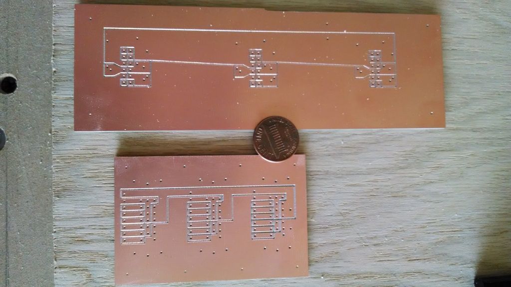
Made more progress this weekend. I machined another circuit board for my honda connector breakout boards for the encoder connectors. I once again made this on my router. I needed the isolation paths to be narrower than circuit board for the power supply. I used a 90° chamfer bit to cut the traces. I also surfaced my spoilboard prior to cuting the board to make sure it was flatter than the last one. I could not afford significant difference in width and depth of the isolation paths. I once again spot drilled the hole locations and manually drilled the holes through and to size after cutting the board.
I also made a breakout board for the connectors for the hall sensors on the servo motors. Same process applied.
Here is a picture of both boards and a penny for size reference. This is after cutting but prior to manual drilling.
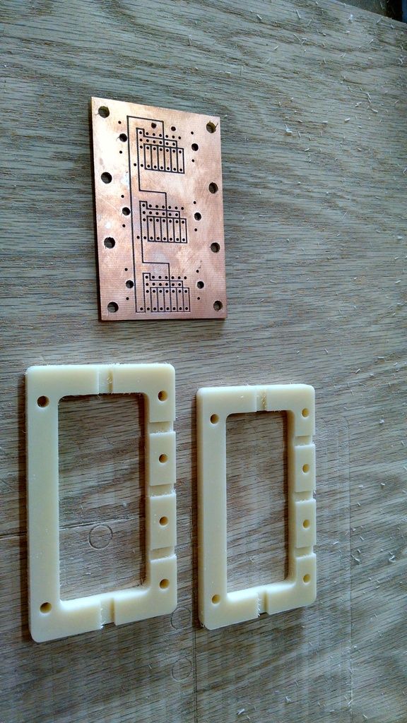
Here is a picture of the encoder board and the mounting brackets that grip the cat 5 cables and the power cable.
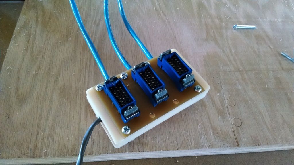
Here is a picture of the assembly after soldering from the top showing the honda connectors.
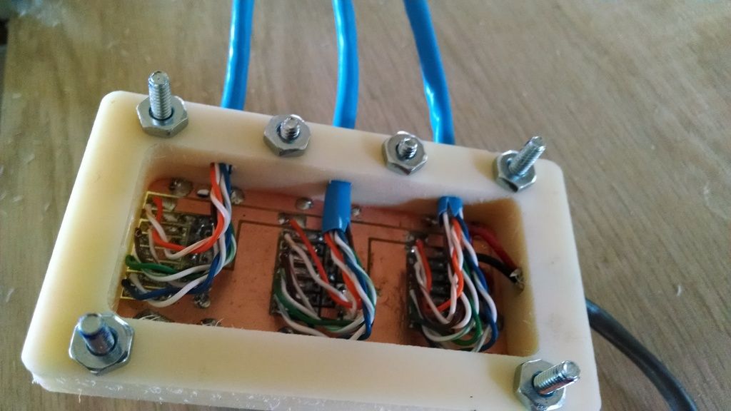
Here is the underside of the assembly.
Please Log in or Create an account to join the conversation.
- LearningLinuxCNC
-
 Topic Author
- Offline
- Elite Member
-

Less
More
- Posts: 319
- Thank you received: 48
01 Jun 2015 08:30 - 01 Jun 2015 08:32 #59289
by LearningLinuxCNC
Replied by LearningLinuxCNC on topic RB1-CNC Retrofit
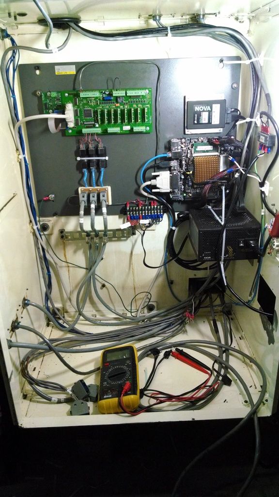
I then assembled the encoder breakout board to the main control board and made adapters for the differential to single ended encoder converters. And i wired it all up to the Pico UPC.
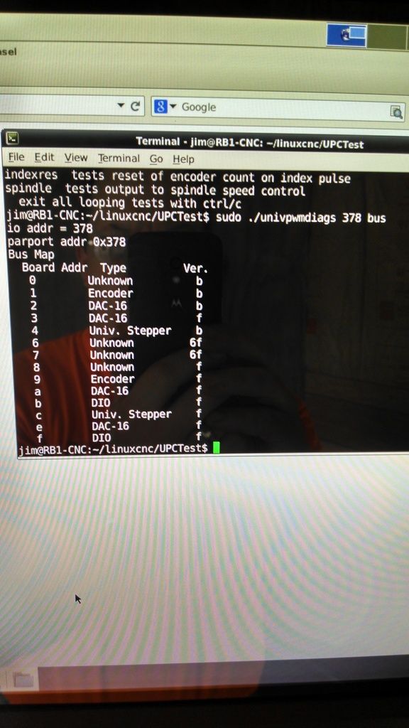
Then it was time to test the Pico UPC. I downloaded the UPC diagnostic program from the Pico website. I then started running the test as recommended by Jon. I ran the following test:
sudo ./univpwmdiags 378 bus
and I got the following results:
This did not seem right as it should have indicated that there was a UPC connected to port 0. Also everytime i would rerun the test I would get different results. Very weird I thought.
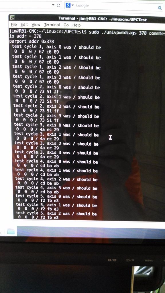
Anyway I decided to test the communication further with the following test:
sudo ./univpwmdiags 378 commtest
and received the following results.
This did not seem right either as the communications were failing every attempt. I could not figure it out at all. So I left to go to supper with the family. On the way I realized that I did not have power connected to the UPC board. As Homer Simpson would say DOH!
When I returned home from supper I connected power to the UPC and everything worked perfectly. I was able to get all of the tests to work correctly and I was even able to get the encoder changes on the X axis to show up in LinuxCNC. Making major progress now. Spent the rest of my time doing additional wiring to the machine. I now have the inputs wired up. I have the power all wired up to the VFDs and I have the PWM and Direction signals wired from the UPC board to the servo drives.
This week I will be working on additional wiring to get all of the outputs connected. I will assemble the breakout board for the hall sensors and I will be doing additional test on the inputs outputs etc. I will do a dry run with the VFDs to make sure they work using the front panel controls then I will work on getting them to work with LinuxCNC.
Hopefully this week I will do some videos of the testing and setup process in LinuxCNC. Hoping to have it operational by the end of next weekend. Still have lots to do but it never hurts to have high goals.
Last edit: 01 Jun 2015 08:32 by LearningLinuxCNC.
Please Log in or Create an account to join the conversation.
- LearningLinuxCNC
-
 Topic Author
- Offline
- Elite Member
-

Less
More
- Posts: 319
- Thank you received: 48
04 Jun 2015 09:59 #59418
by LearningLinuxCNC
Replied by LearningLinuxCNC on topic RB1-CNC Retrofit
OK, I have been doing some testing with LinuxCNC and the Pico UPC board. I have my inputs wired up to the board and I am testing as much as possible before I connect outputs. I have tested the e-stop circuit. I have my e-stop button, and end of axis hard limit switches all wired in series in the e-stop circuit. If I trip any one of the switches the e-stop circuit is broken and it trips out the e-stop in LinuxCNC. This all works if I don't have the watchdog enabled on the UPC board.
Now I need some help. If I enable the watchdog on the UPC board and I restart LinuxCNC and the Axis UI the machine will not come out of e-stop because the PWM's are not being enabled. In the HAL files the axis pin axis.0.amp-enable-out is tied to the ppmc.0.pwm.00.enable via a signal Xenable. Same goes for the other two axis. The reason that the watchdog keeps the e-stop circuit broken is that the axis.0.amp-enable-out is always false. What makes the amp-enable-out pins go true?
Now I need some help. If I enable the watchdog on the UPC board and I restart LinuxCNC and the Axis UI the machine will not come out of e-stop because the PWM's are not being enabled. In the HAL files the axis pin axis.0.amp-enable-out is tied to the ppmc.0.pwm.00.enable via a signal Xenable. Same goes for the other two axis. The reason that the watchdog keeps the e-stop circuit broken is that the axis.0.amp-enable-out is always false. What makes the amp-enable-out pins go true?
Please Log in or Create an account to join the conversation.
- andypugh
-

- Offline
- Moderator
-

Less
More
- Posts: 23377
- Thank you received: 4966
04 Jun 2015 17:32 #59421
by andypugh
That is rather unconventional, and will cause problems.
Normally the limit switches are connected to the axis.N.pos-lim-sw and neg-lim-sw pins in HAL. Typically the e-stop circuit physically disconnects the drives, and a secondary circuit tells LinuxCNC that e-stop has been activated.
A typical simulator hal file containsand the e-stop breaks that short-circuited loop.
For example on my mill the main contactor is operated by an output from iocontrol.0.user-enable-out that passes through the physical e-stop switches and a separate BC switch in the e-stop button feeds the emc-enable-in input. But there are many other ways to do it.
Replied by andypugh on topic RB1-CNC Retrofit
I have my e-stop button, and end of axis hard limit switches all wired in series in the e-stop circuit.
That is rather unconventional, and will cause problems.
Normally the limit switches are connected to the axis.N.pos-lim-sw and neg-lim-sw pins in HAL. Typically the e-stop circuit physically disconnects the drives, and a secondary circuit tells LinuxCNC that e-stop has been activated.
A typical simulator hal file contains
net iocontrol.0.user-enable-out iocontrol.0.emc-enable-inFor example on my mill the main contactor is operated by an output from iocontrol.0.user-enable-out that passes through the physical e-stop switches and a separate BC switch in the e-stop button feeds the emc-enable-in input. But there are many other ways to do it.
Please Log in or Create an account to join the conversation.
- LearningLinuxCNC
-
 Topic Author
- Offline
- Elite Member
-

Less
More
- Posts: 319
- Thank you received: 48
04 Jun 2015 18:27 #59423
by LearningLinuxCNC
Replied by LearningLinuxCNC on topic RB1-CNC Retrofit
Andy,
I am attaching the control wiring schematic for reference. I am using the limit switches in the same configuration as they were used on the original machine. I want the hard limit switches to be an e-stop scenario. I will use software limits for normal operation but If I reach the hard limits I want it to kill the machine with an e-stop. There is a limit override button that releases the hard limit condition so you can move the machine off the limit.
What other problems do you foresee with this configuration?
Jon has said that the issue is not with the axis.#.amp-enable-out but is with something else.
I will post my HAL files a little later once I can get to the machine.
Please Log in or Create an account to join the conversation.
- LearningLinuxCNC
-
 Topic Author
- Offline
- Elite Member
-

Less
More
- Posts: 319
- Thank you received: 48
04 Jun 2015 18:48 #59424
by LearningLinuxCNC
Replied by LearningLinuxCNC on topic RB1-CNC Retrofit
Here is the .ini file for the configuraion
# EMC controller parameters for UPC with threading and pendant

# General note: Comments can either be preceded with a # or ; - either is
# acceptable, although # is in keeping with most linux config files.


# General section -------------------------------------------------------------
[EMC]

# Version of this INI file
VERSION =               $Revision: 1.6 $

# Name of machine, for use with display, etc.
MACHINE =               LinuxCNC-UPC-Thread-Pendant

# Name of NML file to use, default is emc.nml
#NML_FILE =              emc.nml

# Debug level, 0 means no messages. See src/emc/nml_int/emcglb.h for others
 DEBUG =                 0x00000001
# DEBUG =               0x00000007
# DEBUG =               0x7FFFFFFF

# Sections for display options ------------------------------------------------
[DISPLAY]

# Name of display program, e.g., xemc
DISPLAY =             axis
#DISPLAY =             gmoccapy
# DISPLAY =               usrmot
# DISPLAY =    tkemc
# Cycle time, in seconds, that display will sleep between polls
CYCLE_TIME =            0.100

# Path to help file
HELP_FILE =             doc/help.txt

# Initial display setting for position, RELATIVE or MACHINE
POSITION_OFFSET =       RELATIVE

# Initial display setting for position, COMMANDED or ACTUAL
POSITION_FEEDBACK =     ACTUAL

# Highest value that will be allowed for feed override, 1.0 = 100%
MAX_FEED_OVERRIDE =     1.2

# Prefix to be used
PROGRAM_PREFIX = /home/jim/linuxcnc/nc_files

# Introductory graphic
INTRO_GRAPHIC = linuxcnc.gif
INTRO_TIME = 2

# Enable popup balloon help
BALLOON_HELP = 1

#spindle speed VCP
PYVCP = spindle.xml

# Task controller section -----------------------------------------------------
[TASK]

# Name of task controller program, e.g., bridgeporttask
TASK =                  milltask

# Cycle time, in seconds, that task controller will sleep between polls
CYCLE_TIME =            0.010

# Part program interpreter section --------------------------------------------
[RS274NGC]

# File containing interpreter variables
PARAMETER_FILE =        univpwm.var

# Motion control section ------------------------------------------------------
[EMCMOT]

EMCMOT =              motmod

# Key for real OS shared memory, e.g., for simulated motion
SHMEM_KEY =             111

# Timeout for comm to emcmot, in seconds
COMM_TIMEOUT =          1.0

# Interval between tries to emcmot, in seconds
COMM_WAIT =             0.010

# Base task period, in nanoseconds - this is the fastest thread in the machine
BASE_PERIOD =                1000000
# Servo task period, in nanoseconds - will be rounded to an integer multiple
#   of BASE_PERIOD
SERVO_PERIOD =               1000000
# Trajectory Planner task period, in nanoseconds - will be rounded to an
#   integer multiple of SERVO_PERIOD
TRAJ_PERIOD =                10000000

# Hardware Abstraction Layer section --------------------------------------------------
[HAL]

# The run script first uses halcmd to execute any HALFILE
# files, and then to execute any individual HALCMD commands.
#

# list of hal config files to run through halcmd
# files are executed in the order in which they appear
HALFILE =                    univpwm_load.hal
HALFILE =                    univpwm_servo.hal
HALFILE =                    univpwm_io.hal
HALFILE =                    univpwm_motion.hal
#HALFILE =                    pendant.hal
#POSTGUI_HALFILE =            spindle.hal

# list of halcmd commands to execute
# commands are executed in the order in which they appear
#HALCMD =                    save neta

# Trajectory planner section --------------------------------------------------
[TRAJ]

AXES =                  3
# COORDINATES =         X Y Z R P W
COORDINATES =           X Y Z
HOME =                  0 0 0
LINEAR_UNITS =          inch
ANGULAR_UNITS =         degree
CYCLE_TIME =            0.010
DEFAULT_VELOCITY =      0.15
MAX_VELOCITY =          1.20
DEFAULT_ACCELERATION =  5.0
MAX_ACCELERATION =      5.0
PROBE_INDEX =           0
PROBE_POLARITY =        1

# Axes sections ---------------------------------------------------------------

# Important note about OUTPUT_SCALE and PWM_OUTPUT_SCALE
# For this configuration, OUTPUT_SCALE is not used, because
# EMC always overwrites it on shutdown.  So PWM_OUTPUT_SCALE
# was added to hold the scaling.  Someday the OUTPUT_SCALE
# issue may be fixed, and PWM_OUTPUT_SCALE will go away.

# Scaling:  The PWM_OUTPUT_SCALE should be the speed
# in UNITS/second  (inches/sec or mm/sec) that would be
# reached if the PWM duty cycle was 100%.  It depends on
# the power supply voltage, motor RPM/Volt factor, and
# gearing/screw pitch.  For example:
#
# Power supply voltage 50V
# Motor RPM/V     1000RPM/24V
# Gearing:  2 motor revs per 1 screw rev
# Screw pitch: 0.2" per turn
#
# Max motor speed = 50V * 1000RPM/24V = 2083 RPM
# Max screw speed = 2083RPM * 1(screw)/2(motor) = 1041RPM
# Max table speed = 1041RPM * 0.2"/turn = 208 in/min
# Max table speed = 208 in/min / 60 seconds = 3.47 inches/sec
#
# Since max speed is reached at 100% duty cycle, PWM_OUTPUT_SCALE
# should be 3.47

# First axis
[AXIS_0]

TYPE =                          LINEAR
UNITS =                         0.03937007874016
HOME =                          0.000
MAX_VELOCITY =                  1.20
MAX_ACCELERATION =              5.0
PID_MAX_VEL =              1.2
BACKLASH = 0.000
CYCLE_TIME =                    0.001000
INPUT_SCALE =                   -128000
OUTPUT_SCALE = -1
MIN_LIMIT =                     -12.0
MAX_LIMIT =                     0.1
FERROR = 0.1
MIN_FERROR = 1.0
HOME_OFFSET =                    0.0
HOME_SEARCH_VEL =                0.5
HOME_LATCH_VEL =                 0.1
HOME_USE_INDEX =                 YES
HOME_IGNORE_LIMITS =             NO
DEADBAND =                         2e-05
P =                              1000
I =                              2.5
D =                                1
BIAS =                             0
FF0 =                              0
FF1 =                              0.42
FF2 =                              0.0125


# Second axis
[AXIS_1]

TYPE =                          LINEAR
UNITS =                         0.03937007874016
HOME =                          0.000
MAX_VELOCITY =                  1.20
MAX_ACCELERATION =              3.0
PID_MAX_VEL =              1.2
BACKLASH = 0.000
CYCLE_TIME =                    0.001000
INPUT_SCALE =                   -128000
OUTPUT_SCALE = -1
MIN_LIMIT =                     -10.0
MAX_LIMIT =                     10.0
FERROR = 0.002
MIN_FERROR = 1.005
HOME_OFFSET =                    0.0
HOME_SEARCH_VEL =                0.5
HOME_LATCH_VEL =                 0.1
HOME_USE_INDEX =                 YES
HOME_IGNORE_LIMITS =             NO
DEADBAND =                         7e-06
P =                              3000
I =                              2.5
D =                                40
BIAS =                             0
FF0 =                              0
FF1 =                              0.6
FF2 =                              0.001

# Third axis
[AXIS_2]

TYPE =                          LINEAR
UNITS =                         0.03937007874016
HOME =                          0.0
MAX_VELOCITY =                  1.20
MAX_ACCELERATION =              3.0
PID_MAX_VEL =              1.2
BACKLASH = 0.000
CYCLE_TIME =                    0.001000
INPUT_SCALE =                   128000
OUTPUT_SCALE = 1
MIN_LIMIT =                     -10.0
MAX_LIMIT =                     10.0
FERROR = 0.002
MIN_FERROR = 0.005
HOME_OFFSET =                    0.0
HOME_SEARCH_VEL =                0.5
HOME_LATCH_VEL =                 0.1
HOME_USE_INDEX =                 YES
HOME_IGNORE_LIMITS =             NO
DEADBAND =                         0.000075
P =                              1500
I =                              10
D =                                1.5
BIAS =                             0
FF0 =                              0
FF1 =                              0.3
FF2 =                              0.007


# section for main IO controller parameters -----------------------------------
[EMCIO]

# Name of IO controller program, e.g., io
EMCIO =     io

# cycle time, in seconds
CYCLE_TIME =    0.100

# tool table file
TOOL_TABLE =    univpwm.tbl

# section for external NML server parameters ----------------------------------
[EMCSERVER]
# Uncomment the following line if you need to run a remote GUI.
# EMCSERVER =           emcsvr
Please Log in or Create an account to join the conversation.
- LearningLinuxCNC
-
 Topic Author
- Offline
- Elite Member
-

Less
More
- Posts: 319
- Thank you received: 48
04 Jun 2015 18:49 #59425
by LearningLinuxCNC
Replied by LearningLinuxCNC on topic RB1-CNC Retrofit
Here is the first HAL file univpwm_load.hal
# loads all HAL modules for Universal PWM controller with threading
# this version activates velocity estimation in the PPMC driver
#     with the timestamp=xx parameter in the loadrt line
#     this will only work with rev 4 UPC firmware and EMC2.4.6 or later

# kinematics
loadrt trivkins
# motion controller, get name and thread periods from ini file
loadrt [EMCMOT]EMCMOT base_period_nsec=[EMCMOT]BASE_PERIOD servo_period_nsec=[EMCMOT]SERVO_PERIOD traj_period_nsec=[EMCMOT]SERVO_PERIOD key=[EMCMOT]SHMEM_KEY

# next load the PID module, for four PID loops
loadrt pid num_chan=4

# install Universal PWM Controller driver
loadrt hal_ppmc port_addr="0x378" timestamp="0x00"

# load realtime portion of scope, just to have it handy
loadrt scope_rt

# make some signals for the scope for tuning.
loadrt ddt count=4
loadrt not count=1
loadrt estop_latch count=1
loadrt and2 count=1
loadrt or2 count=1
loadrt conv_s32_float count=1
loadrt mult2 count=2
loadrt lowpass count=1

# set up the realtime thread
# read inputs first
addf ppmc.0.read       servo-thread
# then run the motion controller
addf motion-command-handler servo-thread
addf and2.0            servo-thread
addf estop-latch.0     servo-thread
addf motion-controller servo-thread
addf not.0	       servo-thread
# then the PID loops
addf pid.0.do-pid-calcs servo-thread
addf pid.1.do-pid-calcs servo-thread
addf pid.2.do-pid-calcs servo-thread
addf pid.3.do-pid-calcs servo-thread
#  for spindle
addf or2.0              servo-thread
addf conv-s32-float.0   servo-thread
addf mult2.0            servo-thread
addf mult2.1            servo-thread
addf lowpass.0          servo-thread
# write outputs last
addf ppmc.0.write servo-thread
Please Log in or Create an account to join the conversation.
- LearningLinuxCNC
-
 Topic Author
- Offline
- Elite Member
-

Less
More
- Posts: 319
- Thank you received: 48
04 Jun 2015 18:50 #59426
by LearningLinuxCNC
Replied by LearningLinuxCNC on topic RB1-CNC Retrofit
Here is the second HAL file univpwm_servo.hal
# HAL config file for servos -- expanded from core_servo.hal
# for a full four axis setup

# create four position feedback signals
newsig Xpos-fb float
newsig Ypos-fb float
newsig Zpos-fb float

# connect position feedback to PID loop
net Xpos-fb => pid.0.feedback
net Ypos-fb => pid.1.feedback
net Zpos-fb => pid.2.feedback

# connect position feedback to motion module
net Xpos-fb => axis.0.motor-pos-fb
net Ypos-fb => axis.1.motor-pos-fb
net Zpos-fb => axis.2.motor-pos-fb

# create PID to DAC output signals
newsig Xoutput float
newsig Youtput float
newsig Zoutput float

# connect output signals to output of PID loops
net Xoutput <= pid.0.output
net Youtput <= pid.1.output
net Zoutput <= pid.2.output
setp pid.0.maxoutput [AXIS_0]PID_MAX_VEL

# set PID loop output limits to +/-1.00
setp pid.1.maxoutput [AXIS_1]PID_MAX_VEL
setp pid.2.maxoutput [AXIS_2]PID_MAX_VEL

# set PID loop gains
setp pid.0.Pgain [AXIS_0]P
setp pid.0.Igain [AXIS_0]I
setp pid.0.Dgain [AXIS_0]D
setp pid.0.bias [AXIS_0]BIAS
setp pid.0.FF0 [AXIS_0]FF0
setp pid.0.FF1 [AXIS_0]FF1
setp pid.0.FF2 [AXIS_0]FF2
setp pid.0.deadband [AXIS_0]DEADBAND

setp pid.1.Pgain [AXIS_1]P
setp pid.1.Igain [AXIS_1]I
setp pid.1.Dgain [AXIS_1]D
setp pid.1.bias [AXIS_1]BIAS
setp pid.1.FF0 [AXIS_1]FF0
setp pid.1.FF1 [AXIS_1]FF1
setp pid.1.FF2 [AXIS_1]FF2
setp pid.1.deadband [AXIS_1]DEADBAND

setp pid.2.Pgain [AXIS_2]P
setp pid.2.Igain [AXIS_2]I
setp pid.2.Dgain [AXIS_2]D
setp pid.2.bias [AXIS_2]BIAS
setp pid.2.FF0 [AXIS_2]FF0
setp pid.2.FF1 [AXIS_2]FF1
setp pid.2.FF2 [AXIS_2]FF2
setp pid.2.deadband [AXIS_2]DEADBAND

# create four position command signals
newsig Xpos-cmd float
newsig Ypos-cmd float
newsig Zpos-cmd float

# connect position commands to motion controller
net Xpos-cmd <= axis.0.motor-pos-cmd
net Ypos-cmd <= axis.1.motor-pos-cmd
net Zpos-cmd <= axis.2.motor-pos-cmd

# connect position commands to PID input
net Xpos-cmd => pid.0.command
net Ypos-cmd => pid.1.command
net Zpos-cmd => pid.2.command

# create bit signals to enable/disable the PID loops
newsig Xenable bit
newsig Yenable bit
newsig Zenable bit

# connect the signals to the motion controller
net Xenable <= axis.0.amp-enable-out
net Yenable <= axis.1.amp-enable-out
net Zenable <= axis.2.amp-enable-out

# connect the signals to the PID blocks
net Xenable => pid.0.enable
net Yenable => pid.1.enable
net Zenable => pid.2.enable
Please Log in or Create an account to join the conversation.
Time to create page: 0.110 seconds

