what to do with a free scrap dumpster find ?
- machinedude
-
 Topic Author
- Offline
- Platinum Member
-

Less
More
- Posts: 715
- Thank you received: 312
13 Aug 2021 07:24 - 13 Aug 2021 07:25 #217664
by machinedude
Replied by machinedude on topic what to do with a free scrap dumpster find ?
i thought this was interesting when you over speed a motor by running it past the the rated 60 Hz. The ratio of decrease is the same as a mechanical gearing in the torque department. So running a a 60 Hz motor at 120 Hz cuts the torque in half at 120 Hz the same way a pulley 2 times the size of the other would in a mechanical system. 24 N/m of torque at 100% 16 N/m running at 90 Hz @ 67 % and 12 N/m running at 120 Hz @ 50% torque
AT the lowest torque @12 N/m that's quite a bit of spindle force and in theory that is spinning the motor @ 7200RPM other factors play into these number so in reality they will be lower but that seems about on track for a machine tool .
i seen this Hitachi drive has a boost feature for low speed and can go as low as .5 HZ or about 30 RPM in th-s case. this drive might be pricey but it does quite a bit. should be able to add an encoder and be able to do rigid tapping from what i can tell so far. it will take a PP/R of up to 1024.
i have to admit HP is misleading when it comes to spindles and it's more about the range of torque over the range of speed you can get from your set up. 3HP might be overkill but i don't think a cushion will hurt. i would rather have more than needed than not enough")
AT the lowest torque @12 N/m that's quite a bit of spindle force and in theory that is spinning the motor @ 7200RPM other factors play into these number so in reality they will be lower but that seems about on track for a machine tool .
i seen this Hitachi drive has a boost feature for low speed and can go as low as .5 HZ or about 30 RPM in th-s case. this drive might be pricey but it does quite a bit. should be able to add an encoder and be able to do rigid tapping from what i can tell so far. it will take a PP/R of up to 1024.
i have to admit HP is misleading when it comes to spindles and it's more about the range of torque over the range of speed you can get from your set up. 3HP might be overkill but i don't think a cushion will hurt. i would rather have more than needed than not enough
Last edit: 13 Aug 2021 07:25 by machinedude.
Please Log in or Create an account to join the conversation.
- machinedude
-
Topic Author
- Offline
- Platinum Member
-
Less
More
- Posts: 715
- Thank you received: 312
14 Aug 2021 12:54 #217746
by machinedude
Replied by machinedude on topic what to do with a free scrap dumpster find ?
happen to come across this video on spindles with VFD drives and rigid tapping. this young fellow is spot on with my findings and put together i very nice video to stream line the process. the set up he has is basically the same as what i was thinking about doing with the exception of my spindle being a horizontal rather than vertical like his.
i have noticed a few going with a 4 pole motor with a base speed of 1800 rpm. so to talk about that. the 4 pole motors do better at low rpm torque so slower speeds will have better torque but the need to have great low end torque at very low speeds is a trade off at the torque at higher speeds. with a base speed at 1800rpm by the time you get to 3600 rpm the base 60 Hz is now running at 120 Hz and the torque has been cut in half already from the rated torque.so it's true they can deliver full torque at 6 Hz or a 180 rpm if it's a 4 pole motor but they suffer on the top end as a result it seems. and not to mention the price is about double compared to the one i am looking at.
so that would be the only difference in choices i would make. i will have to look at drives a little more at automation direct since that was where i found the motor i like.
Please Log in or Create an account to join the conversation.
- machinedude
-
Topic Author
- Offline
- Platinum Member
-
Less
More
- Posts: 715
- Thank you received: 312
22 Aug 2021 21:17 - 22 Aug 2021 22:24 #218440
by machinedude
Replied by machinedude on topic what to do with a free scrap dumpster find ?
i got to starting attaching the table to the saddle and adding rails adds about 1 5/8 of a inch to the table height; i would imagine i will pick up another 1 5/8 once the ways are attached to the box ways. so some sort of way cover are probably going to have to be dreamed up for this project later on. the extra height will cut into the travel some i would think too but i never know how much until i build something but the height is actually a good thing since once a table top is on the Y axis on a horizonal configuration would be useful to go slightly under the table top. i could see it coming in handy doing weld preps or just edge breaks. so this will be something to think about as i go.
on a plus note i did check with an indicator across the grinders table just sitting on the rails not attached and in 2 directions the surface was flat within .0007 at the most. it might get better once the rails are attached? regardless it was a good sign things are pretty flat. the spacing was based on the location of the oil ports in the casting so i may end up spreading them apart more and drilling and tapping new holes? just depends on any flex once extended? the table casting is 2" thick and i was planning on mounting a steel sub plate over top of the entire table for a 9" x 31" table top so it might be fine as is? will check to see if it deflects any once the rails are attached to the table bottom.
in case your wondering yes i'm flying by the seat of my pants on this project seems to be a common theme for me
since this machine had a flat on flat way and a V way on the other side the two rails will not be on the same plane. so in order to get things set i had to figure out the offset height between the two. since my indicator only moved .0007 over 6" i would say i am probably about as close as i can get with a tired old Bridgeport
but the height is actually a good thing since once a table top is on the Y axis on a horizonal configuration would be useful to go slightly under the table top. i could see it coming in handy doing weld preps or just edge breaks. so this will be something to think about as i go.on a plus note i did check with an indicator across the grinders table just sitting on the rails not attached and in 2 directions the surface was flat within .0007 at the most. it might get better once the rails are attached? regardless it was a good sign things are pretty flat. the spacing was based on the location of the oil ports in the casting so i may end up spreading them apart more and drilling and tapping new holes? just depends on any flex once extended? the table casting is 2" thick and i was planning on mounting a steel sub plate over top of the entire table for a 9" x 31" table top so it might be fine as is? will check to see if it deflects any once the rails are attached to the table bottom.
in case your wondering yes i'm flying by the seat of my pants on this project
seems to be a common theme for me
since this machine had a flat on flat way and a V way on the other side the two rails will not be on the same plane. so in order to get things set i had to figure out the offset height between the two. since my indicator only moved .0007 over 6" i would say i am probably about as close as i can get with a tired old Bridgeport
Attachments:
Last edit: 22 Aug 2021 22:24 by machinedude. Reason: correction
The following user(s) said Thank You: tommylight
Please Log in or Create an account to join the conversation.
- tommylight
-

- Offline
- Moderator
-

Less
More
- Posts: 21734
- Thank you received: 7425
22 Aug 2021 21:58 #218443
by tommylight
Replied by tommylight on topic what to do with a free scrap dumpster find ?
Very nice.
Please Log in or Create an account to join the conversation.
- machinedude
-
Topic Author
- Offline
- Platinum Member
-
Less
More
- Posts: 715
- Thank you received: 312
24 Aug 2021 08:40 #218599
by machinedude
Replied by machinedude on topic what to do with a free scrap dumpster find ?
i'm pretty sure i have the covering of the ways sorted out. i had some rails that were around 8" longer than the main table section. after moving things around and seeing how things were going to work i decided to cut the extra off those rails so they are flush with the ends of the main table section. the grinder had table extensions that bolt to each end. that will add a shield to protect the moving parts from the top. by going this route i can just skirt the sides to cover the exposed area. makes things simple i like simple i was going to try to gain some travel but i decided to pass on the messing around since the extra travel was not well supported.
so i can only get about 21" of travel max but it should be good rigid movement. the plan is to keep the motor and ball screw in the saddle so it's all covered at all times. the table ends i can probably bend some sheet up and wrap under on the ends to seal things better too. i don't have much clearance over the top of the motor and the rib that runs under the table where the original rack attached to will have to be cleared out over the motor and the other end could serve as a attaching point to drive the table.
got a idea on ball screw length and ended up going with 20mm with a 5 mm lead. i was going to try and get 25mm ball screws but they are few and far between on the cheap and length options. 20mm should work ok too i think.
once i get to the head axis going up and down that is where the fun should start since i have some serious weight there. i figure i have two options a set of gas struts or a counter weight? gas struts would probably be the simplest to counter the weight. but a counter weight would add more mass to the machine and help hinder vibrations. i'm not sure how many cycles gas struts will take before they go bad? a counter weight would probably be the best way to go for long term trouble free operation.
i was going to try to gain some travel but i decided to pass on the messing around since the extra travel was not well supported.so i can only get about 21" of travel max but it should be good rigid movement. the plan is to keep the motor and ball screw in the saddle so it's all covered at all times. the table ends i can probably bend some sheet up and wrap under on the ends to seal things better too. i don't have much clearance over the top of the motor and the rib that runs under the table where the original rack attached to will have to be cleared out over the motor and the other end could serve as a attaching point to drive the table.
got a idea on ball screw length and ended up going with 20mm with a 5 mm lead. i was going to try and get 25mm ball screws but they are few and far between on the cheap and length options. 20mm should work ok too i think.
once i get to the head axis going up and down that is where the fun should start since i have some serious weight there. i figure i have two options a set of gas struts or a counter weight? gas struts would probably be the simplest to counter the weight. but a counter weight would add more mass to the machine and help hinder vibrations. i'm not sure how many cycles gas struts will take before they go bad? a counter weight would probably be the best way to go for long term trouble free operation.
Please Log in or Create an account to join the conversation.
- machinedude
-
Topic Author
- Offline
- Platinum Member
-
Less
More
- Posts: 715
- Thank you received: 312
01 Sep 2021 07:35 - 01 Sep 2021 09:11 #219315
by machinedude
Replied by machinedude on topic what to do with a free scrap dumpster find ?
i started working on the motor mount for the X axis and the ball screw i ordered showed up today so hopefully this weekend since it is a 3 day weekend i can get a decent amount done and post some more progress pictures. i did order some shaft coupling but i did not realize the delivery date was so far out but i did manage to find some that don't need modified so that's a plus at least. would have been nice to have those for the long weekend to finalize the mounting of the bearing blocks for the ball screw but that is not happening so on to plan B to keep moving forward. i plan to slot the end bearing block mounting point so i have some wiggle room. i'm trying to do every thing i can with my current set up before i take the saddle off the mill. it's a bit of a bear to move around by hand
i did make another set of mounting brackets for the bearing trucks for the cross axis. i actually made those from the mounting points on the saddle, so basically the saddle ended up being my fixture to hold those brackets bit of a pain but better than ripping everything off to put a vise on the table
have a motor, vfd and braking resistor on hand so the expensive parts are out of the way. now i just get nickel and dimed to death getting odds and ends sorted out sometimes i feel like this is a addiction more than a hobby
i did make another set of mounting brackets for the bearing trucks for the cross axis. i actually made those from the mounting points on the saddle, so basically the saddle ended up being my fixture to hold those brackets
bit of a pain but better than ripping everything off to put a vise on the table have a motor, vfd and braking resistor on hand so the expensive parts are out of the way. now i just get nickel and dimed to death getting odds and ends sorted out
sometimes i feel like this is a addiction more than a hobby
Last edit: 01 Sep 2021 09:11 by machinedude.
The following user(s) said Thank You: tommylight
Please Log in or Create an account to join the conversation.
- OT-CNC
- Offline
- Platinum Member
-
Less
More
- Posts: 617
- Thank you received: 75
01 Sep 2021 15:30 #219345
by OT-CNC
Replied by OT-CNC on topic what to do with a free scrap dumpster find ?
Interesting project. May I ask how much deflection do you get at extreme travel? Measuring approx. where the grinding wheel would be and table overhanging each end. Push down at the table in the wheel area and see if you notice any indicator readings. I would also check the far end to see how much play there is. I would also check under the wheel area when sliding the table back and forth. Any deflection may look like wheel hop in a grind. You'll have to check that directly off the base casting not measuring through the flex of the BP.
I saw this this post too late, but I would have recommended moglice as an option. Although I personally only have used that material for nut rebuild and casting alignment.
If you want to improve the .0007" error on your mounting, I would scrape it in.
I saw this this post too late, but I would have recommended moglice as an option. Although I personally only have used that material for nut rebuild and casting alignment.
If you want to improve the .0007" error on your mounting, I would scrape it in.
Please Log in or Create an account to join the conversation.
- machinedude
-
Topic Author
- Offline
- Platinum Member
-
Less
More
- Posts: 715
- Thank you received: 312
01 Sep 2021 20:25 #219364
by machinedude
Replied by machinedude on topic what to do with a free scrap dumpster find ?
that .0007 was just a quick flatness check with the rails not even attached. it could get better or worse so it's hard to say until things are bolted down properly. same goes for checking deflection. once i have the saddle back in place and the rails all attached deflection checks with an indicator will be done to make another evaluation.
i do know this the table bottom had .015 to .020 of wear so the wear strips that were original to the grinder did good protecting the covered surfaces but also did a good job of holding the grit on top and destroying the uncovered surfaces of the table bottom.
i also found that the oil ports were blocked so that could have been a major factor for the extreme table wear.
long story short this machine was a basket case
Please Log in or Create an account to join the conversation.
- machinedude
-
Topic Author
- Offline
- Platinum Member
-
Less
More
- Posts: 715
- Thank you received: 312
04 Sep 2021 23:47 #219640
by machinedude
Replied by machinedude on topic what to do with a free scrap dumpster find ?
spent the day with a angle grinder and a braided wire cup wheel stripping old paint. wire cup wheels work pretty well stripping paint if you have a need. managed to get the base and the extensions for the table painted so now they match the rest this paint seems to be pretty durable so hopefully it holds up over time. i do believe it is and an alkyd enamel
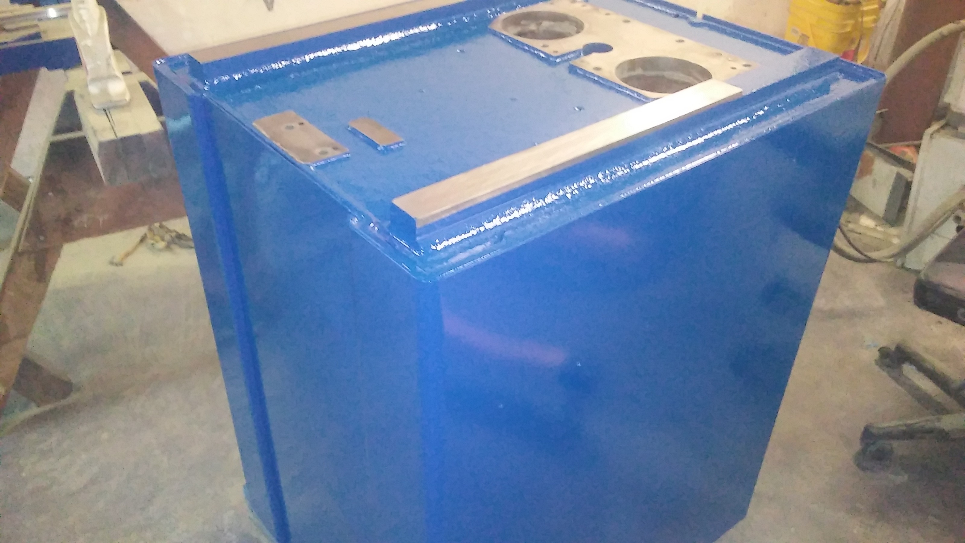
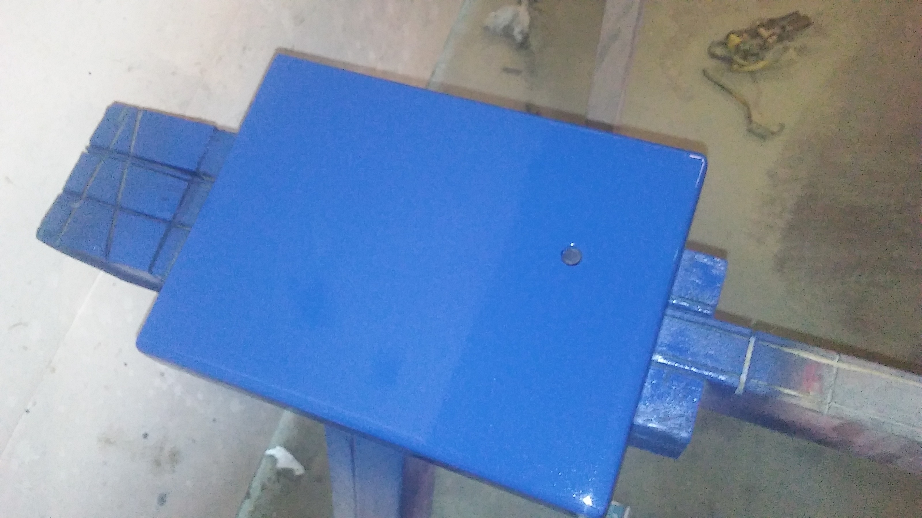
this paint seems to be pretty durable so hopefully it holds up over time. i do believe it is and an alkyd enamel
Attachments:
The following user(s) said Thank You: tommylight
Please Log in or Create an account to join the conversation.
- tommylight
-
- Offline
- Moderator
-
Less
More
- Posts: 21734
- Thank you received: 7425
05 Sep 2021 00:47 #219643
by tommylight
Replied by tommylight on topic what to do with a free scrap dumpster find ?
Nice, i like the color !
The following user(s) said Thank You: machinedude
Please Log in or Create an account to join the conversation.
Time to create page: 0.331 seconds