what to do with a free scrap dumpster find ?
- machinedude
-
 Topic Author
- Offline
- Platinum Member
-

Less
More
- Posts: 715
- Thank you received: 312
05 Sep 2021 12:39 #219663
by machinedude
Replied by machinedude on topic what to do with a free scrap dumpster find ?
i do think this is going to be my duel loop experiment to learn from and come back to the gantry machine later. this free dumpster find has me side tracked ") but in a good kind of way i think i can pick up glass scales pretty cheap they are reasonable in price. i don't think i will need anything over 600 mm long at the most.
but in a good kind of way i think i can pick up glass scales pretty cheap they are reasonable in price. i don't think i will need anything over 600 mm long at the most.
i have a 7i97 for the analog encoder part but need to do something for the VFD spindle end which i think will be analog control as well. probably need to add on for a MPG too but that's getting ahead of the mechanical mess i seemed to have dove into head first when i get the mechanics sorted out i will start getting serious about the electronics.
when i get to the electronics i will be asking a lot of stupid stuff i am sure
but in a good kind of way i think i can pick up glass scales pretty cheap they are reasonable in price. i don't think i will need anything over 600 mm long at the most.i have a 7i97 for the analog encoder part but need to do something for the VFD spindle end which i think will be analog control as well. probably need to add on for a MPG too but that's getting ahead of the mechanical mess i seemed to have dove into head first
when i get the mechanics sorted out i will start getting serious about the electronics.when i get to the electronics i will be asking a lot of stupid stuff i am sure
Please Log in or Create an account to join the conversation.
- machinedude
-
Topic Author
- Offline
- Platinum Member
-
Less
More
- Posts: 715
- Thank you received: 312
05 Sep 2021 20:09 - 05 Sep 2021 21:31 #219695
by machinedude
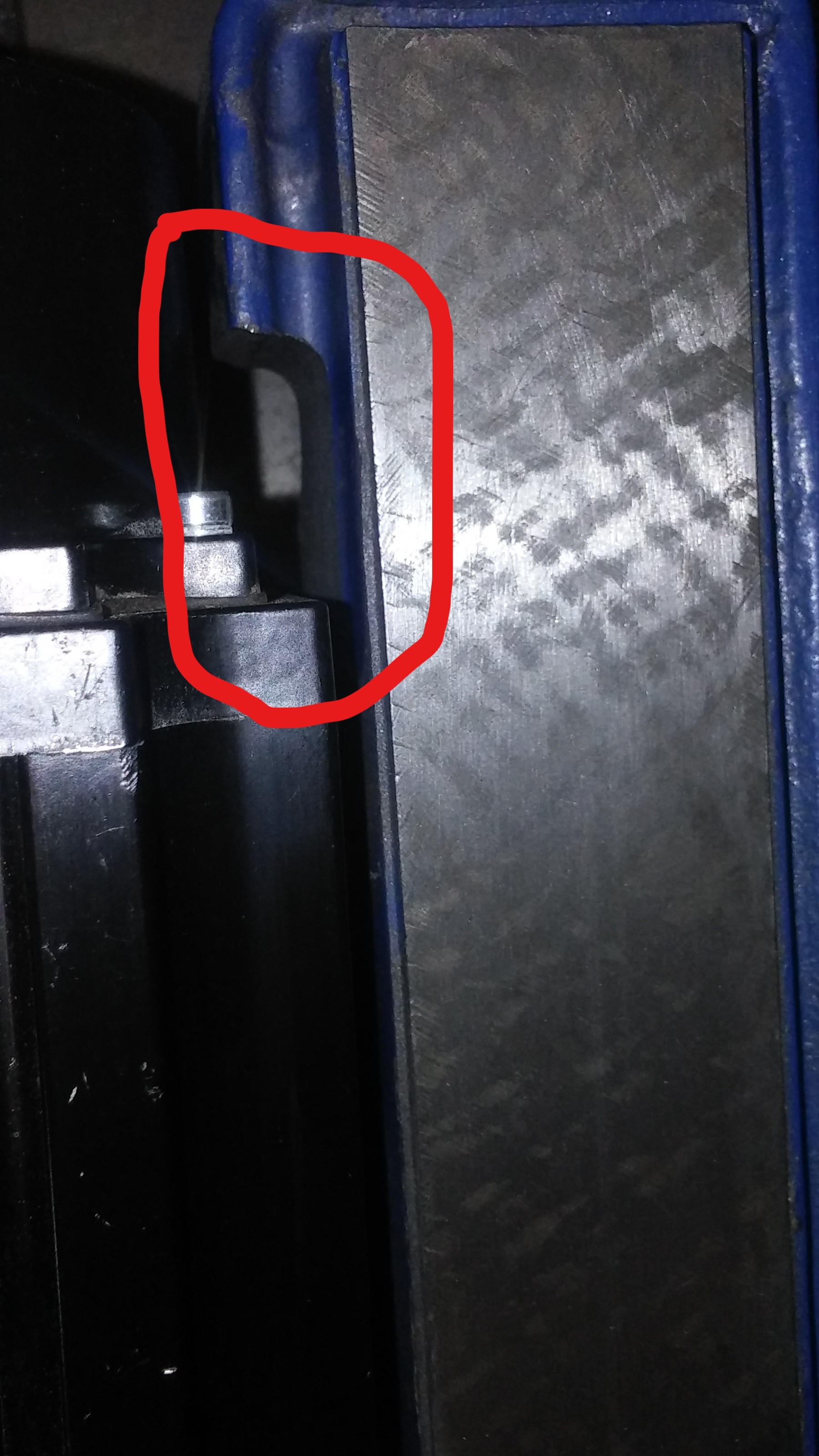
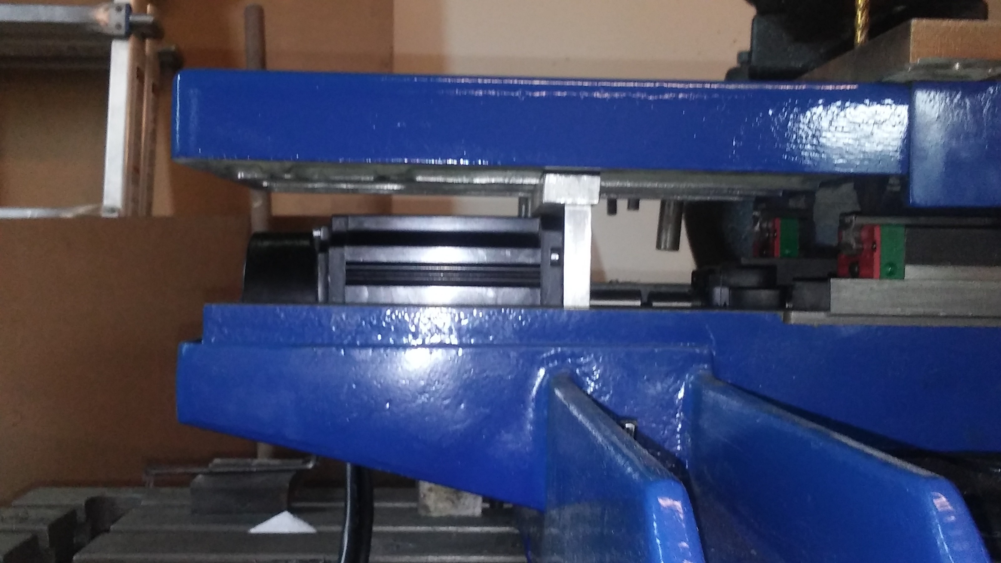
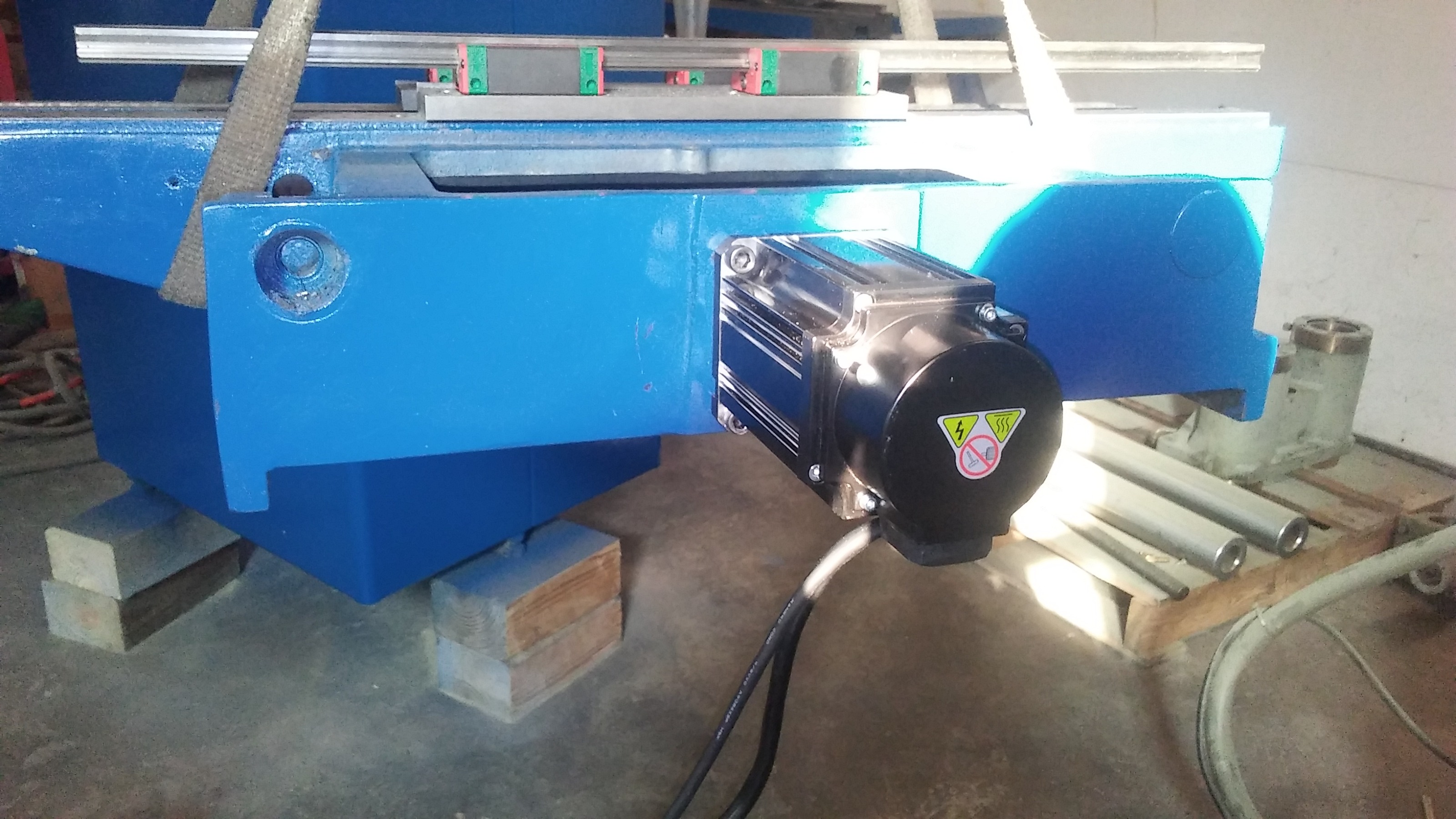
 had to sort out the ball screw and motor mount clearances and have a plan for what needs done. i did mount the floating support end but left the rest for later until i get a shaft coupling in my hands. the fixed bearing block needs a riser block that will double as a attaching point as well. the motor mount clears everything except a web in the center of the table. when i get to the rails mounting holes i can trim it down so it's not an issue. the motor mount needed some clearance for the motor to fit where i wanted and i circled that section on the one side but both sides needed it. the ball screw nut clears the casting so no issues there. i also took a picture of the table extension in place sort of just to show how the motor and ball screw will be covered and not need anything like telescoping way covers. simple solution to a big problem so i will thank myself later for not being greedy and trying to get some extra travel and the mounts are made for the box ways just not attached yet.

Replied by machinedude on topic what to do with a free scrap dumpster find ?
just to show how the motor and ball screw will be covered and not need anything like telescoping way covers. simple solution to a big problem so i will thank myself later for not being greedy and trying to get some extra travel and the mounts are made for the box ways just not attached yet.
Attachments:
Last edit: 05 Sep 2021 21:31 by machinedude.
The following user(s) said Thank You: tommylight
Please Log in or Create an account to join the conversation.
- tommylight
-

- Online
- Moderator
-

Less
More
- Posts: 21625
- Thank you received: 7383
05 Sep 2021 22:58 #219708
by tommylight
Replied by tommylight on topic what to do with a free scrap dumpster find ?
Looking niceeeee !
The following user(s) said Thank You: machinedude
Please Log in or Create an account to join the conversation.
- machinedude
-
Topic Author
- Offline
- Platinum Member
-
Less
More
- Posts: 715
- Thank you received: 312
06 Sep 2021 19:38 #219781
by machinedude
Replied by machinedude on topic what to do with a free scrap dumpster find ?
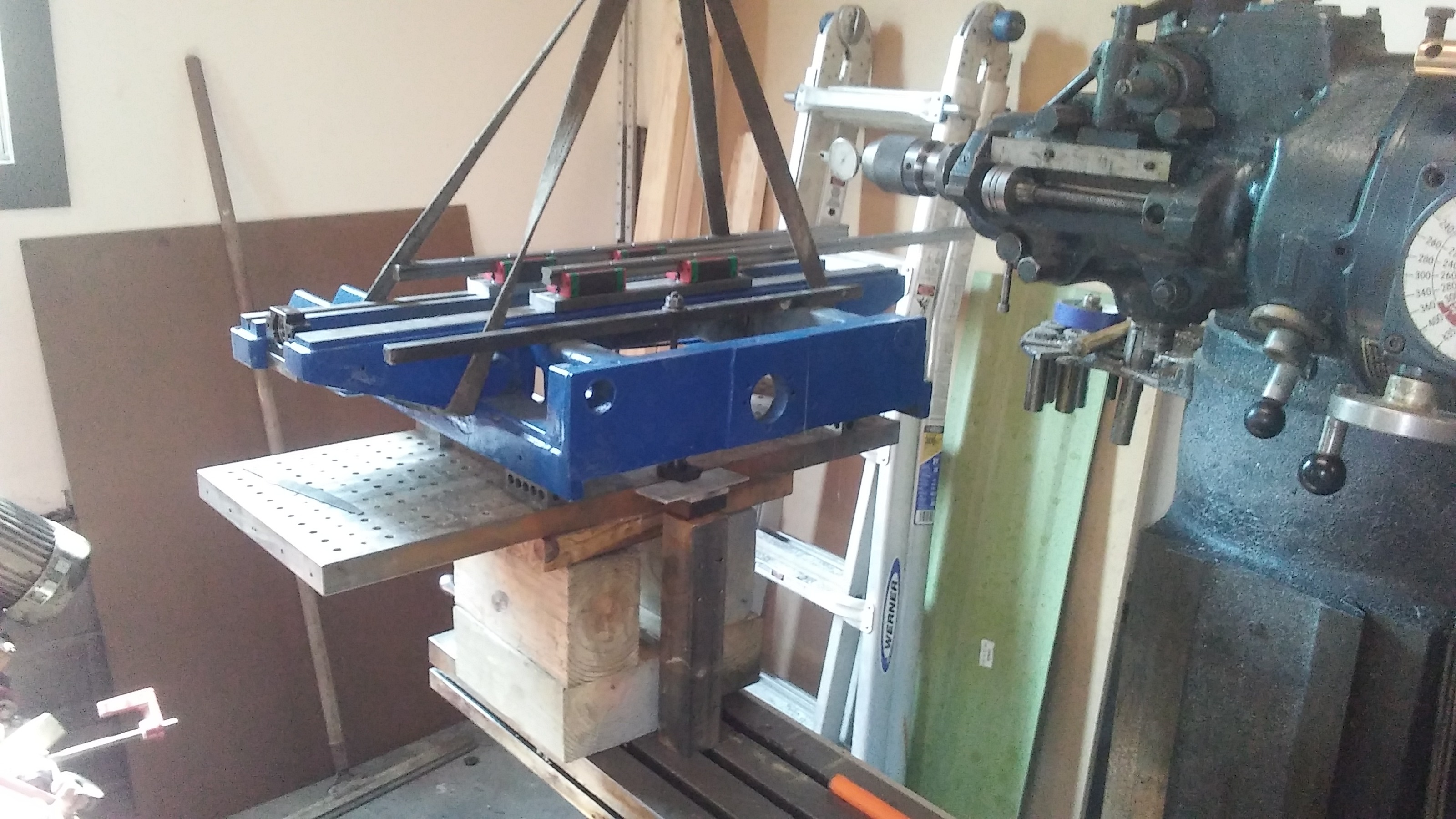
got the rails attached and cleared the obstruction that was in the way. took everything off and put the table on the saddle to check flatness in the only direction i can at the moment and even extended the table about 3/4 of the way and got up on it to see if i could see any defection. i weigh around 200lbs so i would say it is pretty solid so far. i don't see the cross travel being much different the columns for the Y axis is what i am most curious about but that's a ways off before i can check that part.
made a quick video don't mind the mess in the shop i know it needs some attention
vimeo.com/599053252
made a quick video don't mind the mess in the shop i know it needs some attention
vimeo.com/599053252
Please Log in or Create an account to join the conversation.
- machinedude
-
Topic Author
- Offline
- Platinum Member
-
Less
More
- Posts: 715
- Thank you received: 312
13 Sep 2021 20:22 #220501
by machinedude


 some more progress pictures. It's been slow going the way i have to resort to to get things machined. the Bridgeport does not have enough travel to do everything in one shot so i have to establish a center line for the screw and then go as far down as i can and put a datum hole on center of the screw so i can sweep it in after i swing the head on the mill the other way
boring the saddle casting for the cross axis motor was a treat as well wish i had a horizonal mill
Replied by machinedude on topic what to do with a free scrap dumpster find ?
boring the saddle casting for the cross axis motor was a treat as well
wish i had a horizonal mill Attachments:
The following user(s) said Thank You: tommylight
Please Log in or Create an account to join the conversation.
- machinedude
-
Topic Author
- Offline
- Platinum Member
-
Less
More
- Posts: 715
- Thank you received: 312
14 Sep 2021 18:07 #220636
by machinedude
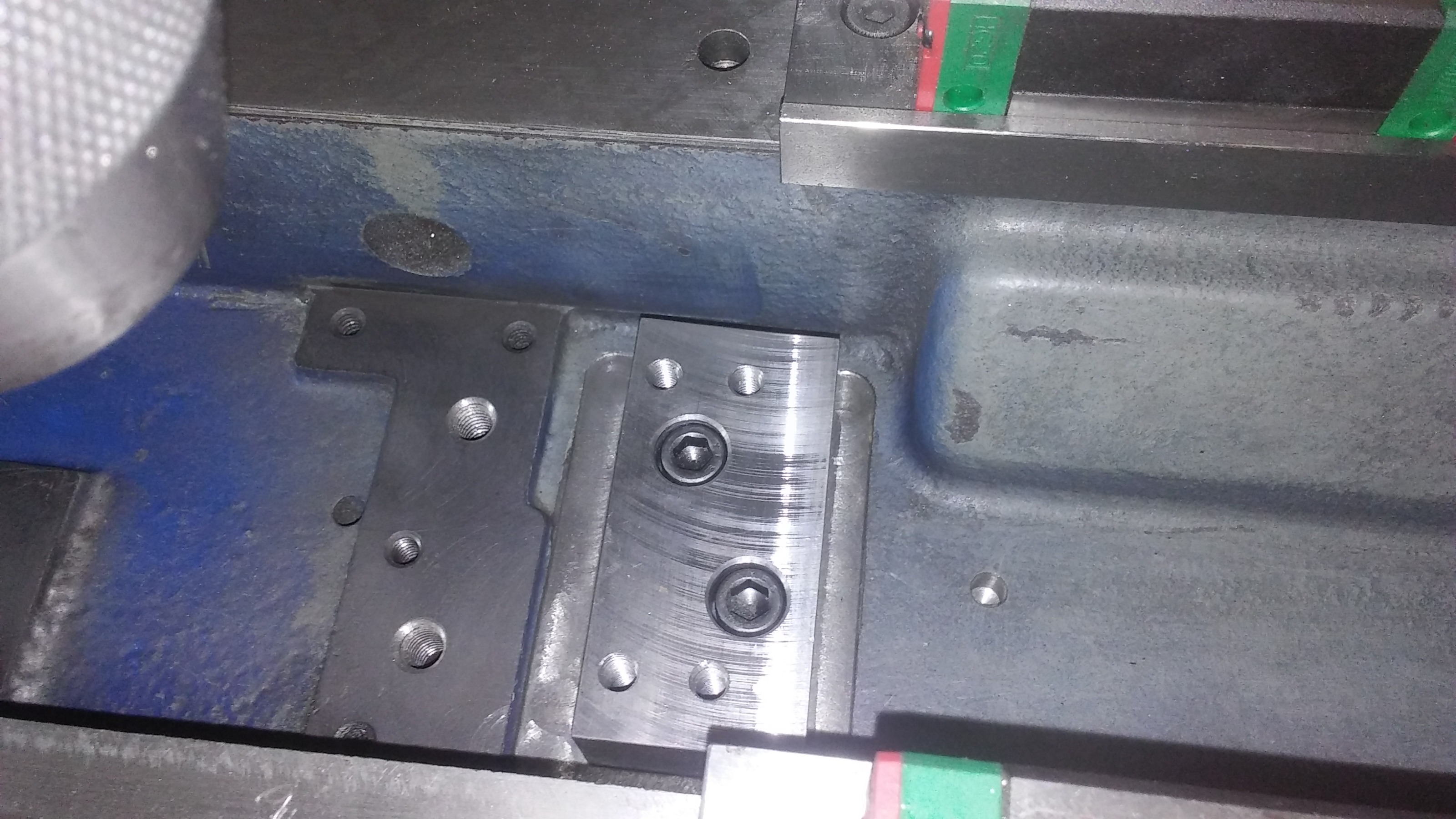
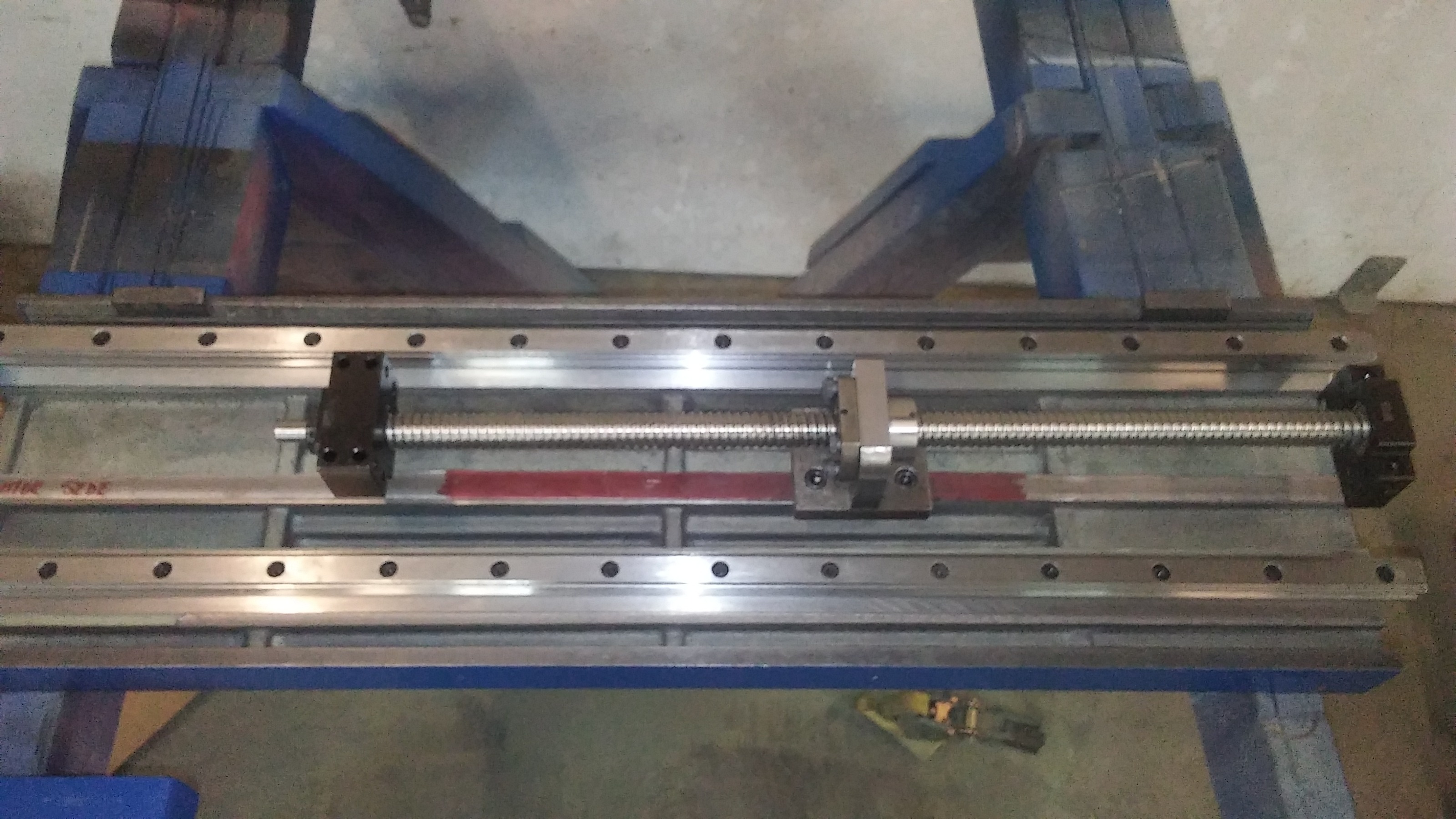 since i had everything up on the mill i got a good set of numbers with the known center line of the screw in relation to the rails so i could work on the drive connections for the table. if all goes well i should be able to assemble the screw and bearing blocks when it goes back together and just have to worry about the fixed and floating bearing block connections. i should be able to get to those connections once the table is on the far end of each of those connections.
Replied by machinedude on topic what to do with a free scrap dumpster find ?
Attachments:
The following user(s) said Thank You: tommylight, johnmc1
Please Log in or Create an account to join the conversation.
- machinedude
-
Topic Author
- Offline
- Platinum Member
-
Less
More
- Posts: 715
- Thank you received: 312
19 Sep 2021 00:52 #221052
by machinedude
Replied by machinedude on topic what to do with a free scrap dumpster find ?
got the bearing block brackets attached to the base and got the rails mounted on the under side of the saddle so this was just a rough assembly to make sure everything went together. i was going to get a 9" x 31" flat of steel for a table top but think i will make due with the 30" x12" x 1.25 thick plate i have already it's already drilled and tapped as a sub plate with dowel holes the extra width will be handy after thinking about it more the assembly was not bad but would be a lot easier with an extra set of hands it stinks it all has to come back apart to sort the rest out but at least it went together
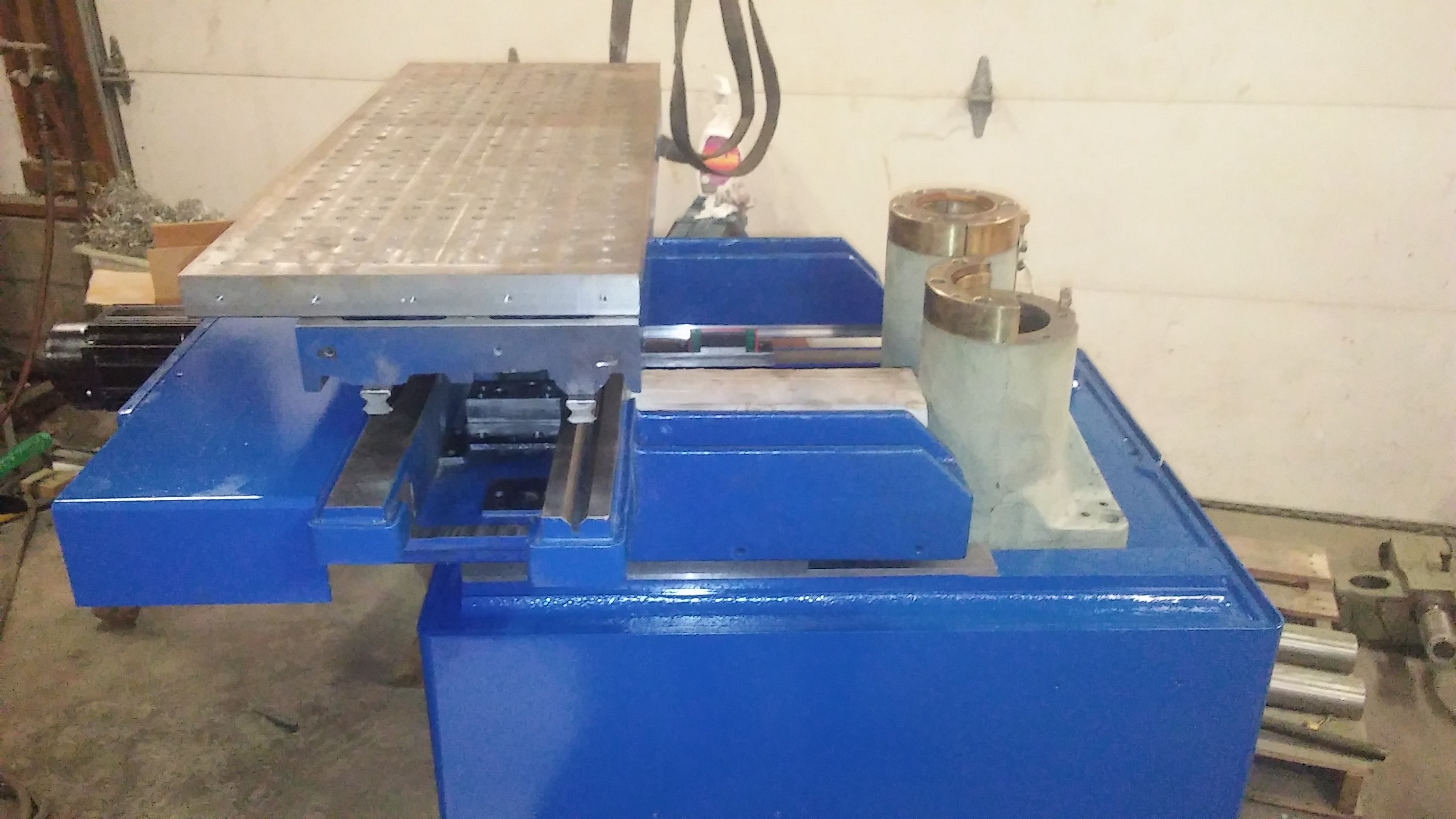
the assembly was not bad but would be a lot easier with an extra set of hands it stinks it all has to come back apart to sort the rest out but at least it went together
Attachments:
The following user(s) said Thank You: tommylight
Please Log in or Create an account to join the conversation.
- machinedude
-
Topic Author
- Offline
- Platinum Member
-
Less
More
- Posts: 715
- Thank you received: 312
03 Oct 2021 20:45 #222133
by machinedude
Replied by machinedude on topic what to do with a free scrap dumpster find ?
well i thought i had it all figured out but i did not land where i thought i would the original set up was done the same way just less travel since nothing was attached and only held by gravity. since the travel is so short critical speed on the screw is not really an issue if i let it float. the best i could have got was about 14 inches but that did not happen but was able to get 11" vs the original 6" but that's not the end of the world since the clearance between the spindle location and cutting area will be more than this. so it will boil down to finding a sweet spot. one of the pictures shows the end of travel so if you have an imagination you can see what i am talking about


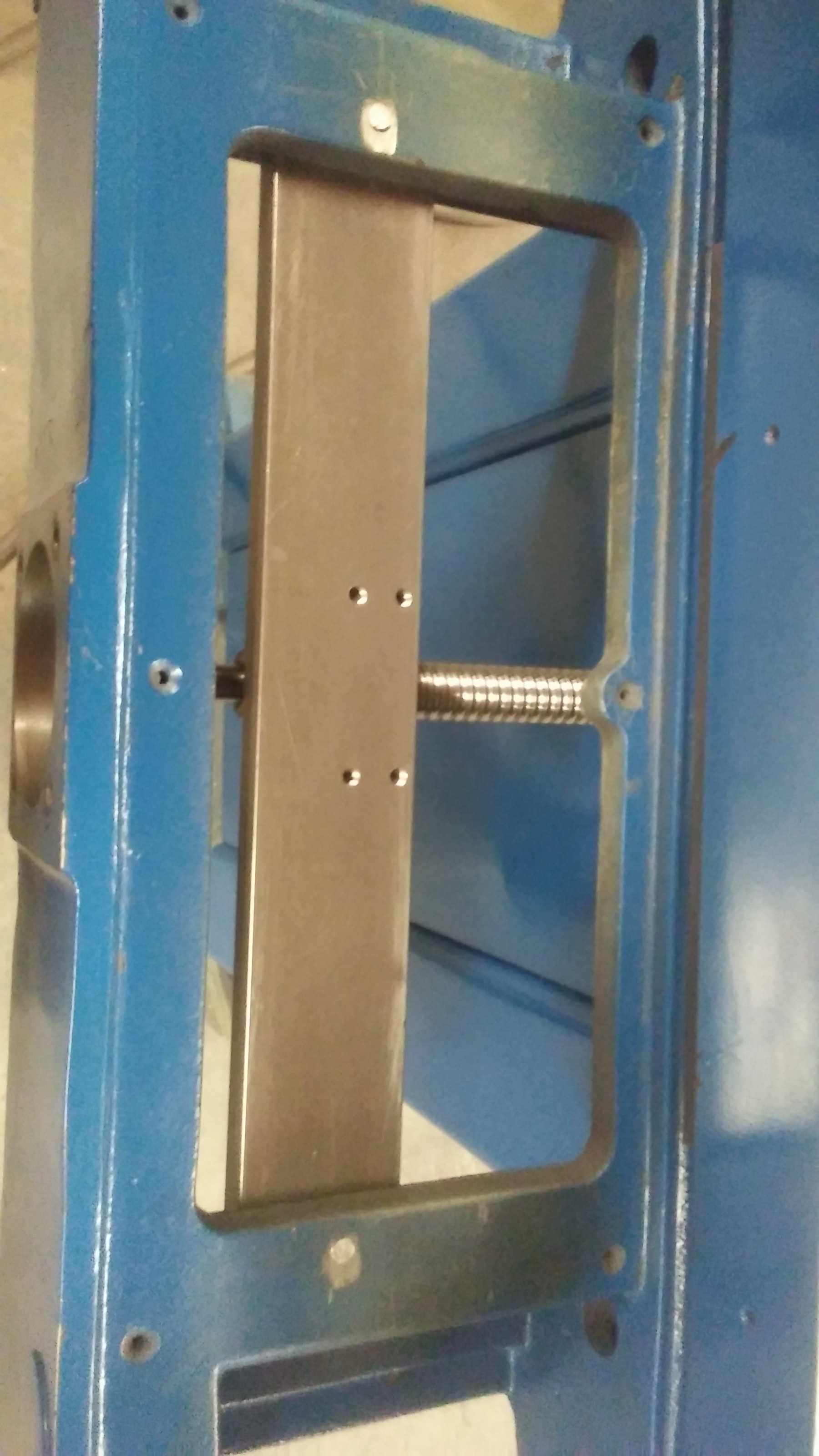

the original set up was done the same way just less travel since nothing was attached and only held by gravity. since the travel is so short critical speed on the screw is not really an issue if i let it float. the best i could have got was about 14 inches but that did not happen but was able to get 11" vs the original 6" but that's not the end of the world since the clearance between the spindle location and cutting area will be more than this. so it will boil down to finding a sweet spot. one of the pictures shows the end of travel so if you have an imagination you can see what i am talking about
Attachments:
Please Log in or Create an account to join the conversation.
- tommylight
-
- Online
- Moderator
-
Less
More
- Posts: 21625
- Thank you received: 7383
03 Oct 2021 20:52 #222134
by tommylight
Replied by tommylight on topic what to do with a free scrap dumpster find ?
Sweet! 11" should do just fine.
The following user(s) said Thank You: machinedude
Please Log in or Create an account to join the conversation.
- machinedude
-
Topic Author
- Offline
- Platinum Member
-
Less
More
- Posts: 715
- Thank you received: 312
17 Oct 2021 20:25 #223414
by machinedude
Replied by machinedude on topic what to do with a free scrap dumpster find ?
spent a week working on my rust bucket truck and had a little bit of time to sort out some CNC stuff for this brain storm this weekend
i was able to get into the spindle to see what was in there from the factory, the bore of the casting is straight through with a sleeve pressed in for the bearings. i think i can press the sleeve out and open up the bore on both ends to to make a new spindle shaft. i had built a BT 30 spindle in the past but i want to keep the casting since its part of the linear way assembly of the original grinder.
the first spindle i made turn out decent it had about .0002 of run out which i was fine with since i made it a little 10 x 21 lathe. the spindle shaft was not to bad to make since the biggest diameter was 2.750 inches, the only thing i would change would be the bearing OD since the casting is a little bit smaller then what i did for a housing on the first one. the first one had 45 x 85 x 16 mm bearings but i can get 45 x 75 x16 mm instead for this one. i think i had a bit of overkill on the first one anyways
but the idea is to keep the same design for the shaft and just modify the diameters for the bearings.
some pictures of the prototype spindle i made before. i was also working on some kind of way cover for the back side. i see to much chips falling down and creating problems but that is still a work in progress but i at least have a plan for it now and have stuff gathered up to make something for it
Attachments:
Please Log in or Create an account to join the conversation.
Time to create page: 1.715 seconds