what to do with a free scrap dumpster find ?

More
4 years 8 months ago #233918 by machinedude
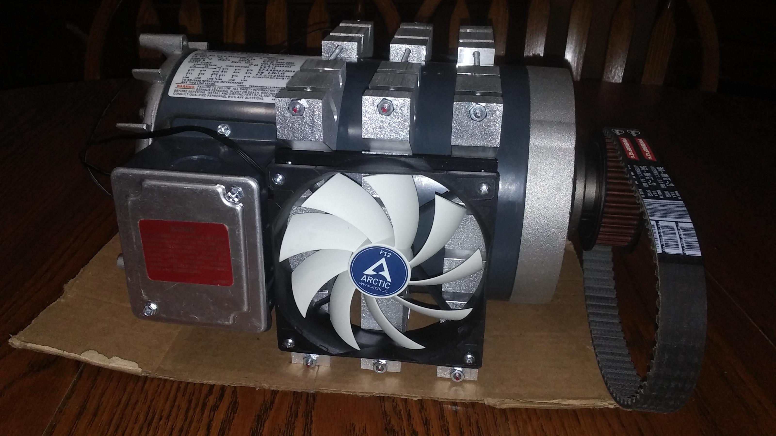
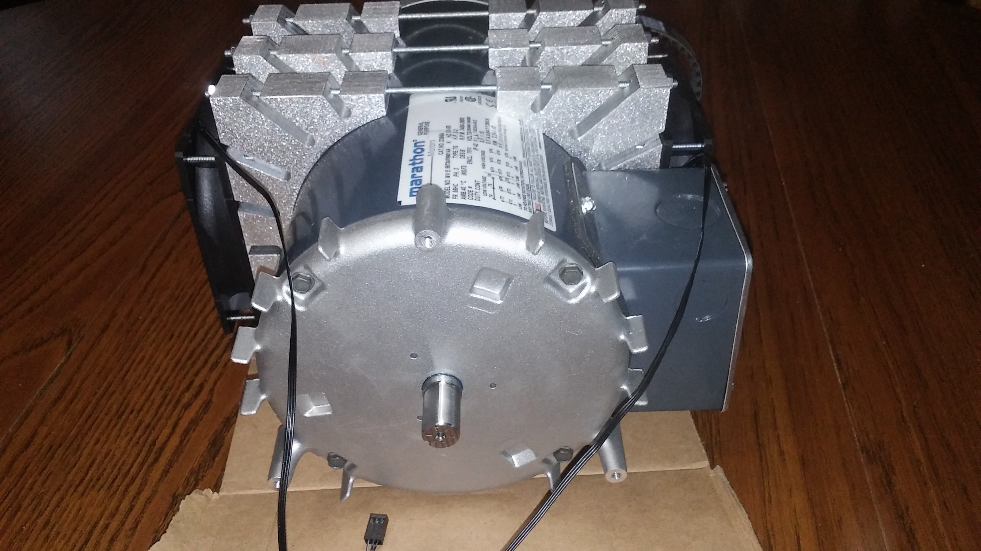
Started  to work on my motor cooling plan and got my heat sinks made and the fans mounted. i think this should work better than the stock motor set up. Since I was testing fit and had things together I figured I would take some picture and share. next step is to alter the shaft on the back end for the encoder and open up the center hole of the plastic cover so it clears the rotary encoder and give it a nice tidy look.


Please Log in or Create an account to join the conversation.

More
4 years 8 months ago #233934 by tommylight
F12 = Flow 120mm
P12 = Pressure 120mm
Fans from Arctic, very good and very cheap so try the P12, should be better for that job.
Also, if you can choose, P12 CO, bearings are long lasting.
The following user(s) said Thank You: machinedude

Please Log in or Create an account to join the conversation.

More
4 years 8 months ago - 4 years 8 months ago #233963 by machinedude
The fans were sitting around and free. My oldest daughter built a gaming PC and bought a bulk lot of them since it was cheaper to buy them that way and used 1 so i had 4 of them sitting here for a while.

with this motor it was rated for constant torque from 345 RPM to 3450 RPM. the slower speeds is where the motor was lacking before with the original fan mounted to the motor shaft. at slower speeds below the rating you run the risk of getting the motor to hot and doing damage this should correct a lot of it i think. the rest of it falls back on the internal wiring and the gauge of wire being able to handle the loads at slower speeds. being an invertor duty motor that part is more robust than a standard 3 phase motor but i don't know how slow i can run it and keep it safe? the motor has plenty of torque so i don't think that would have any issue there since the rated torque is around 18 ft/lbs(24.4 Nm) and the breakdown torque is around 22 ft/lbs,

i looked at some induction motors with encoders and they were not cheap i remember seeing one over $3,000. this motor was retired and i got a deal on it so it was only $350 and the encoder was only $55 so i'm well under $500

servo motors can be had but i think the speeds are limited to around 3,000 RPM so by the time you gear them up to get 5,000 rpm to 6000 rpm you loose half the rated torque and the torque curve is already dropping off before you hit the rated speed on top of that.

running this motor at 90Hz will give me around 5,200 RMP which i feel is a safe limit since the encoder is rated at 6,000 RPM the motor should be safe at this range too, seems to be the normal for over speeding limits with a VFD. i don't know the torque curve for this set up but the drop off starts at above 3450 RPM and with 24.4 Nm of torque it has room for loss at high speeds.

this motor with the mods has a weight of around 50lbs so how much of a weight difference there is between a invertor duty motor and a servo motor in the same range is i don't know? i think a servo could be lighter but it can't be to drastic of a difference i would think?
Last edit: 4 years 8 months ago by machinedude.

Please Log in or Create an account to join the conversation.

More
4 years 8 months ago #234019 by machinedude
i think i have the encoder sorted out for the most part. it turned out to be a little more involved than what i first thought. the end casting of the motor where the bearings are located on that end turned out to not be flat like i thought it was at first. the end has a slight radius to the casing by design, so i had to spot a face to get something flat to mount the encoder to. just like everything else these days there is not a lot of meat on the casting so i wanted to only take what i needed which was hardly anything to keep it strong and as thick as i can.

thinking about how it all goes together was a bit tricky because of how it all goes together, getting to the set screws on the encoder is the problem area. i will have to drill an access hole in the side of the encoder mount and in the side of the plastic cover to be able to get to the set screws for the encoder. but i need to make a trip to the hardware store to get some M4 cap screws. metric and imperial mixed together is enough to make you nuts :)

always some kind of speed bump to get over it seems with this project :)

Please Log in or Create an account to join the conversation.

More
4 years 8 months ago #234072 by machinedude
just some more pictures of how it all turned out. i will admit i did cheat a little and had to extend an allen wrench since a standard length one was not long enough to get to the set screws. i tried to get more pictures but a few did not get saved as i was taking them so i can't show that part. but here is what i have so far.

the encoder mount has a side thru hole into the bore which lines up with the set screws and the plastic cove also has a hole in line with the encoder mount you can see all of this in the pictures. the encoder mount has an undercut in the middle section the reason for this is i did not face a complete surface on the casting so what i ended was a flat ring on the end casting with a high spot in the center, the under cut in the center of the mount is just clearance for the high spot. these castings are paper thin in my opinion. nothing is made well anymore. because things are so thin these days you have ribs cast into the casting and i made the mount before i even seen what was going on inside. but it was tricky getting some tapped hole in the cast to attach the mount and miss the ribs in the casting. it took me a lot of time just to get things lined up to miss all the ribs.


The following user(s) said Thank You: tommylight

Please Log in or Create an account to join the conversation.

More
4 years 8 months ago - 4 years 8 months ago #234129 by machinedude
So while i was working on all this motor stuff i took a closer look at how the old machine drove the lead screw to drive the head up and down the columns. what i found out was more or less the center line distance between the two gears used to do this. the original ratio was 4:1 but that's pretty slow with a 5mm pitch screw even with a servo rated at 5000 RPM. that would only deliver about 250 IMP i can change the ratio to 2:1 and get 500 IMP which is a lot closer to where i would like to be. i can get gears to do this and not get into to heavy of a modification. i actually was able to look the part numbers up and get the pressure angle and pitch diameter of the gears to figure out the spacing. the only issue with gears is backlash. smaller gears have more backlash than the larger sets.

i did see some anti backlash gears that used two gears and spring load them to remove backlash but it looked like something for larger gear sets. timing belts are far better with backlash but the 15mm wide small ones i have played around with are not up to this task. i would probably need something like the drive on the motor at the very least probably something like a 25mm width would even be better.

if anybody has any suggestions i'm all ears :) in the mean time i will look into gates GT4 options and see if i can find a solution there? right now the center line spacing is only 1.875 inches but i could probably open it up another inch if i have too.
Last edit: 4 years 8 months ago by machinedude. Reason: REMOVED SOME BAD INFO.

Please Log in or Create an account to join the conversation.

Time to create page: 0.384 seconds
Powered by Kunena Forum