1 or 2 dedicated 120VAC circuits for my CNC?
- Sray69
- Offline
- Elite Member
-

- Posts: 255
- Thank you received: 13
Yes I do remember that reference. And now it all makes sense.Remember earlier when I said 'belt and suspenders'? My opinion is that a human should be able to turn off all motion and meat-cutting equipment without relying exclusively on software or software-controlled hardware. LCNC is stable, and there are plenty of peoply who rely on software (LCNC or otherwise) for safety stuff. I dont, and that's why I've suggested the scheme presented.
Yeah I know that inductive motors can draw a lot more current at startup than their rated amps. During my research I read they can draw anywhere from 2-7 times the rated amps. My table saws and my dust collection motor have a hard time getting going on the 15A circuits, especially if anything else is drawing from the same circuit.The router should be classified as an inductive load, which means they're rated for 7.5A in the DPDT config. That's technically OK for the router (according to the router specs), but I suspect the contacts won't last a long time.
That reminds me, I would like to figure out a way to switch my dust collection OFF during a fault, E-stop, end of job, etc. I haven't thought through the logistics yet. I may want to have it turn on when the router comes on but not sure. There may be times when I don't want it on while running a job. Either way I would like to figure out how I can accomplish this. The dust collection unit is on the other side of the wall that the CNC is on. I have dust collection conduit running through the wall at the ceiling level above the CNC. I thought I could run 24V +/- from a digital out on the Mesa up the wall and attach it to the conduit and run it through the wall to the outlet that the collector is plugged into. I thought about just getting one of the IoT Power Strips and connect the 24V wires to it. I am sure this is not the cheapest way but definitely the quickest/easiest way.I've got one of the AD 782 DPDT relays switching a 12A vacuum on a router table, and another one switching a 10A(ish) coolant pump and they're doing fine after a couple of years of steady service.
That is my next step is laying it all out. I am pretty sure I have some room to breathe in my cabinet for now, but as I upgrade I am sure it will go quick.Next step is playing tetris with all the components in the enclosure. Leave yourself plenty of room if you can, otherwise you'll be using foreceps to get the wires in the component terminals.
Please Log in or Create an account to join the conversation.
- Sray69
- Offline
- Elite Member
-
- Posts: 255
- Thank you received: 13
I am sure some of this is overkill. I also have a bunch of 20AWG wire on hand if there are any circuits that I can use it on. What gauge do you use and/or recommend for what circuits?
Please Log in or Create an account to join the conversation.
- spumco
- Offline
- Platinum Member
-

- Posts: 2120
- Thank you received: 880
Main to 120VAC terminal block - 10AWG
120 block to contactor - 12AWG
Contactor to 60v PSU and router relay - 12AWG
120 block to 24v PSU - 18AWG
All the DC circuits can be 20AWG
Neutrals & grounds sizes to match the hot line for various circuits.
10AWG & larger is a pain to work with - super stiff and needs to be pre-bent before sticking in terminals & components. Anything smaller than 20 or 22 is also a pain to work with - too small for clumsy hands.
The power cord from the box to the recepticle should be 10/3 SJOOW (30A).
To put the icing on the cake, get a copy (internet) of NFPA-79. That has all the standard wire colors for various circuit voltages & functions, as well as a good reference for terminology.
Please Log in or Create an account to join the conversation.
- spumco
- Offline
- Platinum Member
-
- Posts: 2120
- Thank you received: 880
That reminds me, I would like to figure out a way to switch my dust collection OFF during a fault, E-stop, end of job, etc. I haven't thought through the logistics yet. I may want to have it turn on when the router comes on but not sure. There may be times when I don't want it on while running a job. Either way I would like to figure out how I can accomplish this. The dust collection unit is on the other side of the wall that the CNC is on. I have dust collection conduit running through the wall at the ceiling level above the CNC. I thought I could run 24V +/- from a digital out on the Mesa up the wall and attach it to the conduit and run it through the wall to the outlet that the collector is plugged into. I thought about just getting one of the IoT Power Strips and connect the 24V wires to it. I am sure this is not the cheapest way but definitely the quickest/easiest way.
That IOT power strip can't handle a 24v signal. It takes either 3.3/5vdc or 120vac.
You could put another relay in the box, feed it 120vac from the contactor output, and control it with 24vdc from the Mesa. The relay's 120vac output goes over to the IOT thing and turns the dust collector on/off. The relay can be a really low-amp SPST thing - I bet the IOT strip wouldn't pull 0.5A to turn on.
The dust collector is now programmable with an M-code, and the relay shuts off during an estop. Bamma-jamma...
Please Log in or Create an account to join the conversation.
- Sray69
- Offline
- Elite Member
-
- Posts: 255
- Thank you received: 13
Yeah I have a copy. The first time I tried to read through it it was not real easy to follow. I will have to look through it again now that I am starting to understand things better.To put the icing on the cake, get a copy (internet) of NFPA-79. That has all the standard wire colors for various circuit voltages & functions, as well as a good reference for terminology.
Based on the spec sheet...That IOT power strip can't handle a 24v signal. It takes either 3.3/5vdc or 120vac.
But it also states that it is only rated for "AC loads of up to 12 Amps total". The dust collector would not fire up with that many amps. I am intrigued by the idea of designing something myself someday but for now I will just have to turn it on and off manually. Need to keep focused.The universal control voltage 3-48VDC or 12-120VAC allows control from virtually any micro or AC source.
Thanks!
Please Log in or Create an account to join the conversation.
- spumco
- Offline
- Platinum Member
-
- Posts: 2120
- Thank you received: 880
Easy option - mount a small enclosure on the wall where the dust collector mounts and install a contactor in it. Feed it with 120vac. Run a 24vdc signal from Mesa to it - can be a small 18awg cord.
If you're worried about drawing too many amps or EMI or something, you can isolate the Mesa by using a small relay to switch the 24vdc. i.e. Mesa to relay coil, and 24vdc through the relay contacts to the contactor.
Basically a home-brewed version of the IOT thing, but with proper components.
Please Log in or Create an account to join the conversation.
- Sray69
- Offline
- Elite Member
-
- Posts: 255
- Thank you received: 13
I happen to come across this New - Open Box contactor that looks pretty decent. I was thinking that if this is a decent contactor I could use it either for the dust collector or the router and use the Fuji for the other. Much more reasonable price than the Fuji was.
Eaton Contactor 1NC/3NO IP20 24VDC 15.5A 7.5kW DILMC15-01
Please Log in or Create an account to join the conversation.
- spumco
- Offline
- Platinum Member
-
- Posts: 2120
- Thank you received: 880
Spotted these too:
www.ebay.com/itm/204112498551?epid=1918853837
Please Log in or Create an account to join the conversation.
- Sray69
- Offline
- Elite Member
-
- Posts: 255
- Thank you received: 13
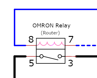
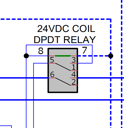
You can see the connection diagram on the top of the relay.
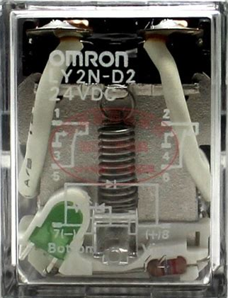
Is this how I would connect these?
Thanks
Attachments:
Please Log in or Create an account to join the conversation.
- Sray69
- Offline
- Elite Member
-
- Posts: 255
- Thank you received: 13
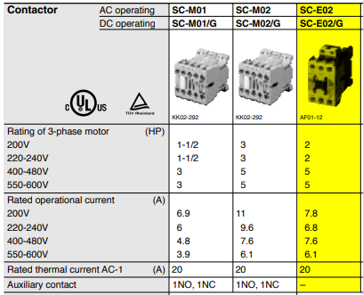
It looks like the Eaton is rated (AC-3) at 15.5A (220V-440V). It does not show a 120V rating either but it is double the Fuji at the same voltages.
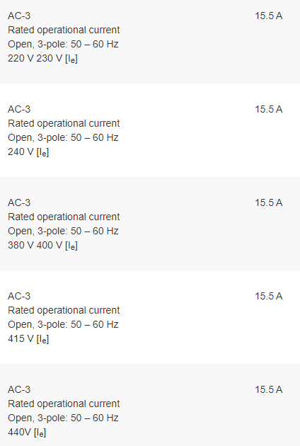
Am I looking at the correct specs? There are so many electrical specs on these components, I have a hard time knowing exactly what I am looking for.
Attachments:
Please Log in or Create an account to join the conversation.