1 or 2 dedicated 120VAC circuits for my CNC?
- spumco
- Offline
- Platinum Member
-

- Posts: 2126
- Thank you received: 882
I did say "and others"... yes, NSK are fabulous. I'd take decent second-hand NSK rails over new no-names any day.
The only caveat I have regarding Omron is I'm pretty sure they're one of (if not the) most counterfeited component brands - for SSR's, proxy's, relays, etc. I'd probably buy a grubby old Omron relay out of a decommissioned machine before I bought a "new-in-box" off ebay.
Thanks for the contact rating clarification!
Please Log in or Create an account to join the conversation.
- Sray69
- Offline
- Elite Member
-

- Posts: 255
- Thank you received: 13
@Tommy: Since you are using a single phase, you can always parallel relay contacts for more current.
two contact points don't always switch at the same time (a slight switching-timing delay occurs between them), thus all loads are instantaneously applied to only a single contact point.
@Sray69: That is interesting. So does this double the current, or is there a calculation to determine what it would be?
I also read that some relays/contactors are specifically rated (read datasheet) for paralleling.Consider that the contacts connected in parallel can’t sustain a current value obtained by the rated current of a single contact multiplied per the number of contacts in parallel. A de-rating must be applied to consider the non-perfect distribution of the current between the contacts in parallel. We will have to consider for 2 contacts in parallel a multiple of 1.6, for 3 contacts 2.2 and for 4 contacts 2.8.For example:
If we have a contact with a rated current in AC-1 category of 25A, connecting 3 poles in parallel the rated current is 25×2.2 = 55A.
Please Log in or Create an account to join the conversation.
- tommylight
-

- Away
- Moderator
-

- Posts: 21734
- Thank you received: 7427
I never went into such detail, but good to know, thank you.
I know i own a plasma cutter that uses 3 parallel contacts to switch 90A for over 7 years without a single issue, while the contacts are rated at 32A. It does a lot of switching, a lot.
Please Log in or Create an account to join the conversation.
- Sray69
- Offline
- Elite Member
-
- Posts: 255
- Thank you received: 13
I am trying to understand how the ON/OFF switch circuit works in your diagram.
So when the cabinet is powered on, power is allowed through the OFF button circuit ,because it is in a CLOSED (NC) state. The power then hits the ON button circuit but is stopped because the circuit is in an OPEN (NO) state. This means that the relay coil is not energized so the poles are open, not allowing power to flow through. Once the ON button is pressed the circuit closes, in turn powering the relay coil, closing the poles allowing power through. Is this correct so far?
If so, I have been struggling to understand how the rest of the circuit works. The wire that comes off the connection between the ON and OFF buttons that goes to terminal 11 on the relay. I think I may have finally figured it out but wanted to confirm.
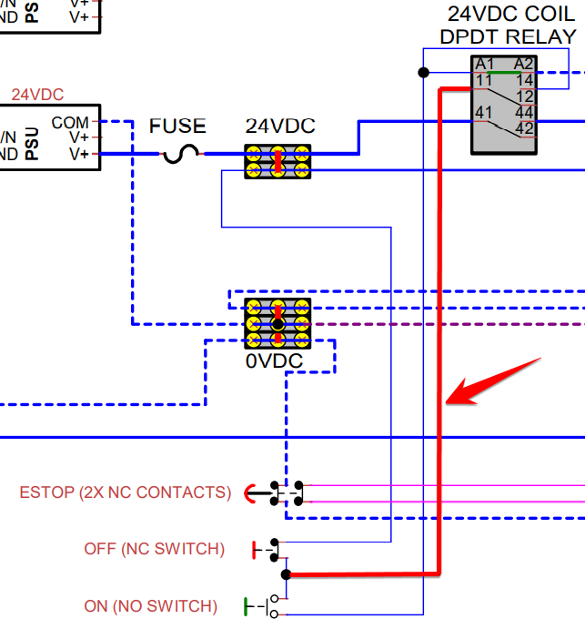
Before the ON button is pressed there is power that goes to terminal 11 but stops because the relay coil is not energized yet. Once the ON button is pressed, the relay coil is energized, closing the poles, connecting the circuits. If I am understanding it correctly, once the ON button is pressed and the poles are closed, the power from terminal 11 flows through to terminal 14 which then powers the wire to the coil, allowing the relay coil to stay energized once the ON button is released. Is this correct?
Sorry if this is confusing or if I am not using the right terminology.
Thanks
Attachments:
Please Log in or Create an account to join the conversation.
- Sray69
- Offline
- Elite Member
-
- Posts: 255
- Thank you received: 13
That is good to know. I now know this is a valid option in certain situations and will keep it in mind in case ever needed.I know i own a plasma cutter that uses 3 parallel contacts to switch 90A for over 7 years without a single issue, while the contacts are rated at 32A. It does a lot of switching, a lot.
Thanks
Please Log in or Create an account to join the conversation.
- spumco
- Offline
- Platinum Member
-
- Posts: 2126
- Thank you received: 882
@spumco-
I am trying to understand how the ON/OFF switch circuit works in your diagram.
Well done!
This relay circuit is called a 'holding' circuit. It's used extensively in machinery and the fundamental purpose is to ensure that the machine does not re-start automatically after a power outage. It's simple & robust.
As you've worked out, the secret is using a DPDT relay where one of the contact pairs is used to 'back-feed' the coil to keep it energized.
An identical arrangement can also used on estop circuits. Some of the machine/safety codes require a second action on the part of the operator to de-assert an estop condition. Installing another holding relay with a separate momentary RESET button will accomplish the goal. The operator has to unlatch the NC estop switch AND press an NO reset button to full de-assert the estop condition.
Please Log in or Create an account to join the conversation.
- Sray69
- Offline
- Elite Member
-
- Posts: 255
- Thank you received: 13
Finally starting to get it!Well done!
Great info! ThanksThis relay circuit is called a 'holding' circuit. It's used extensively in machinery and the fundamental purpose is to ensure that the machine does not re-start automatically after a power outage. It's simple & robust.
Please Log in or Create an account to join the conversation.
- spumco
- Offline
- Platinum Member
-
- Posts: 2126
- Thank you received: 882
Separate reset buttons are used when the estop circuit is more complicated or you want to keep some components energized (sensors, encoders) during an estop while still de-energizing drive/spindle bus power and pneumatic components.
If you want to be super-OCD you could label the ON button as ON/RESET and feel smug.
Please Log in or Create an account to join the conversation.
- Sray69
- Offline
- Elite Member
-
- Posts: 255
- Thank you received: 13
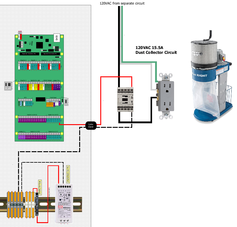
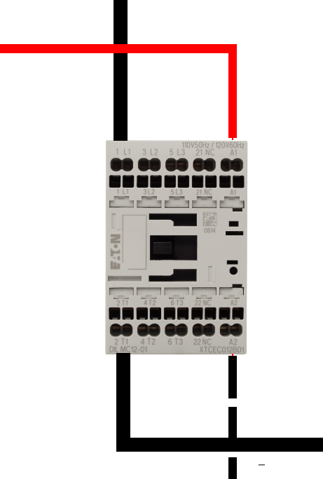
Is this correct?spumco wrote:
Easy option - mount a small enclosure on the wall where the dust collector mounts and install a contactor in it. Feed it with 120vac. Run a 24vdc signal from Mesa to it - can be a small 18awg cord.
Attachments:
Please Log in or Create an account to join the conversation.
- Sray69
- Offline
- Elite Member
-
- Posts: 255
- Thank you received: 13
Attachments:
Please Log in or Create an account to join the conversation.