1 or 2 dedicated 120VAC circuits for my CNC?
- Sray69
- Offline
- Elite Member
-

- Posts: 255
- Thank you received: 13
I am thinking that I need a way to have the pole closed (NC) when power to the cabinet is OFF. I am not sure how to accomplish this though?
Please Log in or Create an account to join the conversation.
- Sray69
- Offline
- Elite Member
-
- Posts: 255
- Thank you received: 13
Would I use the inverted "NOT" state for the 24VDC signal so it would provide power to the contactor when the CNC is not running, keeping the contacts open? Then when the CNC starts I would then have it cut power to the contactor closing the contacts, providing power to the dust collector. Is this correct? Or is this a too simplified approach? Is there more steps needed to make it work better/safer?
Attachments:
Please Log in or Create an account to join the conversation.
- spumco
- Offline
- Platinum Member
-

- Posts: 2114
- Thank you received: 877
Is this correct?
Yep, except for the other Mesa connections (VIN, etc.)
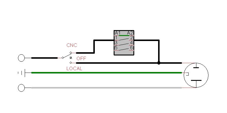
If you're really dead-set on having local/remote control of the vacuum, a 2 or 3-position changover switch mounted at the dust collector recepticle would work. Position 1 is local, position 2 is CNC. Center off if you want a 3-pos. Switch must be rated for full load.
See if this makes sense:
Attachments:
Please Log in or Create an account to join the conversation.
- spumco
- Offline
- Platinum Member
-
- Posts: 2114
- Thank you received: 877
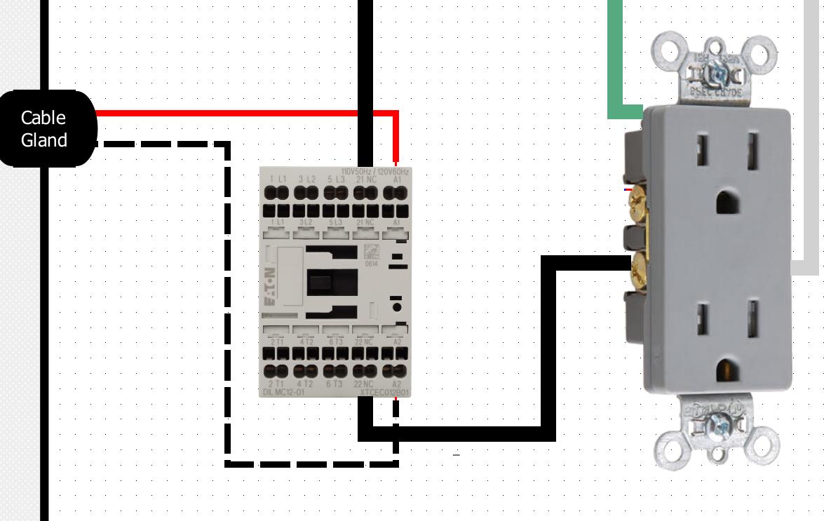
I feel like I am overthinking this. If I use the NC terminal for the 120VAC then when I turn the power to the cabinet off, the dust collector circuit should still have power, correct?
Would I use the inverted "NOT" state for the 24VDC signal so it would provide power to the contactor when the CNC is not running, keeping the contacts open? Then when the CNC starts I would then have it cut power to the contactor closing the contacts, providing power to the dust collector. Is this correct? Or is this a too simplified approach? Is there more steps needed to make it work better/safer?
You're overthinking it. Use the NO contacts, and only supply 24vdc when you want the dust collector to run.
Please Log in or Create an account to join the conversation.
- Sray69
- Offline
- Elite Member
-
- Posts: 255
- Thank you received: 13
Not sure exactly what you mean. Do you mean I am missing all the other Mesa connections for my cabinet? I hid all the other connections in order to just show the dust collector (DC) circuit. If you saw my diagram it is very hard to follow all the circuits. Trying to make it easy to understand.Yep, except for the other Mesa connections (VIN, etc.)
Anyway, did I connect the DC 24VDC wires correctly?
I am good with a 3-way switch. Although I would like to try and relocate it into the CNC room just to make it easier to access and remember. But I can figure that out.
Thanks
Please Log in or Create an account to join the conversation.
- spumco
- Offline
- Platinum Member
-
- Posts: 2114
- Thank you received: 877
And yes, if you hid the other connections to simplify things that's fine. I just didn't want to assume anything when I replied.
Please Log in or Create an account to join the conversation.
- Sray69
- Offline
- Elite Member
-
- Posts: 255
- Thank you received: 13
I had to upload the image to my Google drive because of the size. I wanted it big enough to be able to zoom in. I would appreciate any feedback.
Cabinet Diagram
Thanks
Please Log in or Create an account to join the conversation.
- spumco
- Offline
- Platinum Member
-
- Posts: 2114
- Thank you received: 877
One thing I noticed is that your two estop buttons look...odd. I don't understand why you've got the 24vdc wires split and going to both button contact sets. Since I can't see the actual switch contacts I can't tell which wire pairs are connected via NC, but I think if you push either button the other one will still pass 24vdc to the Mesa input.
Estops should be a chain - wired in series.
You put a ton of work in to that diagram, I get it. But can I suggest you have a go with one of the free circuit diagram software packages? I use TinyCAD, but others here like a couple other (probably better) packages.
Do a forum search for "schematic" or "diagram" in the thread title. There's been a few discussions this year that should pop up and get you going.
Please Log in or Create an account to join the conversation.
- Sray69
- Offline
- Elite Member
-
- Posts: 255
- Thank you received: 13
Originally I was using a E-stop with 1NO (24V - Mesa) and 1NC (120V) . I was told to run the NC in series and the NO in parallel. I guess I forgot to change it so that they are both NC in Series. BTW, I am using the Automation Direct E-stop buttons with the two NC contact blocks.One thing I noticed is that your two estop buttons look...odd. I don't understand why you've got the 24vdc wires split and going to both button contact sets. Since I can't see the actual switch contacts I can't tell which wire pairs are connected via NC, but I think if you push either button the other one will still pass 24vdc to the Mesa input.
Estops should be a chain - wired in series.
The program I am using is a circuit diagram software. It has all the symbols but most of them are confusing and make no sense to me. I just created mine this way so I could use it as a visual guide. I have already spent a solid month and a half (8+ hours a day and weekends) just to figure out all the components I need and how they are connected. I don't want to have to learn all the symbols too. Especially since this is just for my own use.You put a ton of work in to that diagram, I get it. But can I suggest you have a go with one of the free circuit diagram software packages? I use TinyCAD, but others here like a couple other (probably better) packages.
Now you know why I hid all the other conductors in my previous post. LOL. If you download the image you can zoom in much further and see where everything connects. Also the References section shows the terminals for the relays/contactors that may not be very easy to see when zoomed in.That diagram is really hard to follow... where you've used dashed/dotted lines, it's hard (or impossible) to see where they connect to other wires or terminals/components.
Sorry it is hard to understand. I appreciate you taking a look and all the help you have provided. I went ahead and changed the E-stops to both be in Series. Does this look better? I also found one of the dashed black lines was inline/behind one of the red lines so it looked like it didn't go anywhere. I fixed it now.
Updated Diagram
Thanks
Please Log in or Create an account to join the conversation.
- spumco
- Offline
- Platinum Member
-
- Posts: 2114
- Thank you received: 877
I think you nailed it.
Sadly, you're missing some big flashing lights and a motorized disco ball.

Seriously, if you can stomach the additional work, numbering the wires on the diagram and adding labels to the wires as you install them will help in the future.
Please Log in or Create an account to join the conversation.